Asus A88X-PLUS/USB 3.1 A88X-PLUS/USB 3.1 Users manual English - Page 11
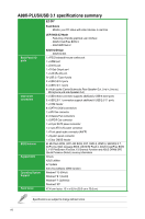
DDR3 DIMM slots, FM2+ APU socket, A88X SATA 6.0Gb/s ports 7-pin SATA6G_1~8
 |
View all Asus A88X-PLUS/USB 3.1 manuals
Add to My Manuals
Save this manual to your list of manuals |
Page 11 highlights
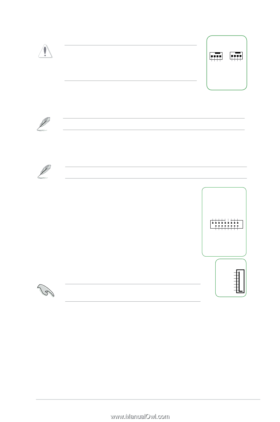
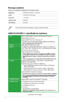
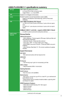
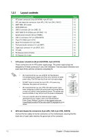
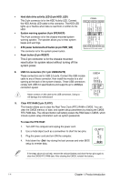
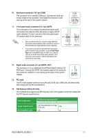
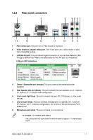
CPU FAN PWM CPU FAN IN CPU FAN PWR GND CHA FAN PWM CHA FAN IN CHA FAN PWR GND Do not forget to connect the fan cables to the fan connectors. Insufficient air flow inside the system may damage the motherboard components. These are not jumpers! Do not place jumper caps on the fan connectors! The APU_FAN connector supports a APU fan of maximum 1A (12 W) fan power. CPU_FAN CHA_FAN 3. AMD® FM2+ APU socket This motherboard comes with a FM2+ socket designed for AMD® A-series and Athlon™Series processors. For more details, refer to Accelerated Processing Unit (APU). 4. DDR3 DIMM slots Install 2 GB, 4 GB, 8 GB, and 16 GB unbuffered non-ECC DDR3 DIMMs into these DIMM sockets. For more details, refer to System memory. 5. USB 3.0 connector (20-1 pin USB3_12) This connector allows you to connect a USB 3.0 module for additional USB 3.0 front or rear panel ports. With an installed USB 3.0 module, you can enjoy all the benefits of USB 3.0 including faster data transfer speeds of up to 5Gbps, faster charging time for USB-chargeable devices, optimized power efficiency and backward compatibility with USB 2.0. USB3_12 PIN 1 USB3+5V IntA_P1_SSRXIntA_P1_SSRX+ GND IntA_P1_SSTXIntA_P1_SSTX+ GND IntA_P1_DIntA_P1_D+ GND USB3+5V IntA_P2_SSRXIntA_P2_SSRX+ GND IntA_P2_SSTXIntA_P2_SSTX+ GND IntA_P2_DIntA_P2_D+ 6. AMD® A88X SATA 6.0Gb/s ports (7-pin SATA6G_1~8) These ports connect to SATA 6.0 Gb/s hard disk drives via SATA 6.0 Gb/s signal cables. When using hot-plug and NCQ, set the SATA Mode Selection item in the BIOS to [AHCI]. SATA6G GND RSATA_TXP RSATA_TXN GND RSATA_RXN RSATA_RXP GND 7. System panel connector (20-5 pin PANEL) This connector supports several chassis-mounted functions. • System power LED (4-pin PWR_LED) This 4-pin connector is for the system power LED. Connect the chassis power LED cable to this connector. The system power LED lights up when you turn on the system power, and blinks when the system is in sleep mode. ASUS A88X-PLUS/USB 3.1 1-3
-
 1
1 -
2
-
3
-
4
-
5
-
 6
6 -
 7
7 -
 8
8 -
 9
9 -
 10
10 -
 11
11 -
 12
12 -
 13
13 -
 14
14 -
 15
15 -
 16
16 -
17
-
18
-
19
-
20
-
21
-
22
-
23
-
24
-
25
-
26
-
27
-
28
-
29
-
30
-
31
-
32
-
33
-
34
-
35
-
36
-
37
 |
 |