Asus AT3N7A-I User Manual
Asus AT3N7A-I - Motherboard - Mini ITX Manual
 |
UPC - 610839172351
View all Asus AT3N7A-I manuals
Add to My Manuals
Save this manual to your list of manuals |
Asus AT3N7A-I manual content summary:
- Asus AT3N7A-I | User Manual - Page 1
AT3N7A-I Motherboard - Asus AT3N7A-I | User Manual - Page 2
Product warranty or service will not be extended if: (1) the product is repaired, modified or altered, unless such repair, modification of alteration is authorized in writing by ASUS; or (2) the serial number of the product is defaced or missing. ASUS PROVIDES THIS MANUAL "AS IS" WITHOUT WARRANTY OF - Asus AT3N7A-I | User Manual - Page 3
1-16 1.8.1 Installing an operating system 1-16 1.8.2 Support DVD information 1-16 Chapter 2: BIOS information 2-1 2.1 Managing and updating your BIOS 2-1 2.1.1 ASUS Update utility 2-1 2.1.2 ASUS EZ Flash 2 2-2 2.1.3 ASUS CrashFree BIOS 2-3 2.2 BIOS setup program 2-4 2.3 Main menu - Asus AT3N7A-I | User Manual - Page 4
Chipset 2-8 2.4.4 Onboard Devices Configuration 2-9 2.4.5 USB Configuration 2-9 2.4.6 PCI PnP 2-10 2.5 Power menu 2-10 2.5.1 Suspend Mode 2-10 2.5.2 ACPI 2.0 Support 2-11 2.5.3 ACPI APIC Support 2-11 2.5.4 APM Configuration 2-11 2.5.5 Hardware Monitor 2-11 2.6 Boot menu 2-12 2.6.1 Boot - Asus AT3N7A-I | User Manual - Page 5
and, if not installed and used in accordance with manufacturer's instructions, may cause harmful interference to radio communications. However, there substances in our products at ASUS REACH website at http://green.asus.com/english/REACH.htm. DO NOT throw the motherboard in municipal waste. This - Asus AT3N7A-I | User Manual - Page 6
BY AN INCORRECT TYPE. • DISPOSE OF USED BATTERIES ACCORDING TO THE ABOVE BATTERY-RELATED INSTRUCTIONS. Operation safety • Before installing the motherboard and adding devices on it, carefully read all the manuals that came with the package. • Before using the product, ensure that all cables are - Asus AT3N7A-I | User Manual - Page 7
the features of the motherboard and the new technology it supports. • Chapter 2: BIOS information This chapter tells how to change system settings through the BIOS Setup menus. Detailed descriptions of the BIOS parameters are also provided. Conventions used in this guide To ensure that you - Asus AT3N7A-I | User Manual - Page 8
LAN USB Fan rated speed ASUS special features Integrated Dual-Core Intel® Atom™ 330 processor NVIDIA® ION™ 533 MHz Dual channel memory architecture - 2 x 240-pin DIMM sockets support maximum 4GB unbuffered non-ECC 800/667 MHz DDR2 memory modules * Refer to www.asus.com or this user manual for - Asus AT3N7A-I | User Manual - Page 9
connector 1 x 24-pin EATX power connector 1 x 4-pin ATX 12V power connector 8 Mb Flash ROM, AMI BIOS, PnP, DMI2.0, WfM2.0, SMBIOS 2.5, ACPI v2.0a 2 x Serial ATA cables 1 x I/O shield 1 x User Manual Drivers ASUS PC Probe II ASUS Update Anti-virus software (OEM version) Mini ITX form factor: 6.75 in - Asus AT3N7A-I | User Manual - Page 10
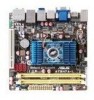
Chapter 1 Product introduction Thank you for buying an ASUS® AT3N7A-I motherboard! Before you start installing the motherboard, and hardware devices on it, check the items in your motherboard package. Refer to page ix for the list of accessories. If any of the items is damaged or missing, contact - Asus AT3N7A-I | User Manual - Page 11
can damage the motherboard. 1.2.2 Layout contents Connectors/Jumpers/Slots/LED 1. ATX power connectors (24-pin EATXPWR, 4-pin ATX12V) 2. CPU, power, and chassis fan connectors (3-pin CPU_FAN, 3-pin PWR_FAN, 3-pin CHA_FAN) 3. USB connector (10-1 pin USB910) 4. Atom 330 processor 5. DDR2 DIMM - Asus AT3N7A-I | User Manual - Page 12
Processing Unit (CPU) The motherboard comes with an onboard Dual-Core Intel® Atom™ 330 processor and a specially designed CPU heatsink and fan. Ensure that the CPU fan cable is connected to the onboard CPU_Fan connector. 1.4 System memory 1.4.1 Overview The motherboard comes with two Double Data - Asus AT3N7A-I | User Manual - Page 13
you are using a 32-bit Windows® OS. - Install a 64-bit Windows® OS when you want to install 4GB memory on the motherboard. • When you install 4GB memory on the motherboard, the memory that the system can detect is less than 4GB. • This motherboard does not support DIMMs made up of 256 megabits - Asus AT3N7A-I | User Manual - Page 14
Package E1108AEBG-8E-F K4T1G084QE Heat-Sink Package D1288TEFCGL25U K4T1G084QE E2108ABSE-8G-E 8ZG27 D9JWB Heat-Sink Package Heat-Sink Package 6 4-4-4-12 5 6 5-5-5-15 5 6 6 6-6-6-12 4-4-4-15 4-4-4-15 DIMM support A* B •• •• (continued on the next page) ASUS AT3N7A-I 1-5 - Asus AT3N7A-I | User Manual - Page 15
inserted into either slot as the single-channel memory configuration. • B*: Supports one pair of modules inserted into both the yellow slots as one pair of dual-channel memory configuration. Visit the ASUS website at www.asus.com for the latest QVL. 1-6 Chapter 1: Product introduction - Asus AT3N7A-I | User Manual - Page 16
, if any. See Chapter 2 for information on BIOS setup. 2. Assign an IRQ to the card. 3. Install the software drivers for the expansion card. 1.5.3 PCI slot The PCI slot supports cards such as a LAN card, SCSI card, USB card, and other cards that comply with PCI specifications. ASUS AT3N7A-I 1-7 - Asus AT3N7A-I | User Manual - Page 17
clear the CMOS memory of date, time, and system setup parameters by erasing the CMOS RTC RAM data. The onboard button cell battery powers the RAM data pins 1-2. 3. Plug the power cord and turn ON the computer. 4. Hold down the key during the boot process and enter BIOS setup to re-enter data. - Asus AT3N7A-I | User Manual - Page 18
Windows® XP, if the Bluetooth Driver item is not displayed on the Support DVD's Drivers screen, follow the steps below: 1. Shut down your computer and switch off the Power Supply Unit (PSU). 2. Switch on the PSU and boot up your computer. 3. Open the Support DVD and click ASUS InstAll. 5. LAN (RJ - Asus AT3N7A-I | User Manual - Page 19
USB 2.0 devices. 14. eSATA port. This port connects to an external Serial ATA hard disk drive. To use hot-plug, set the SATA Mode Select item in the BIOS to [AHCI Mode]. See section 2.3.4 Storage Configuration for details. 15. Optical S/PDIF Out port. This port connects to an external audio output - Asus AT3N7A-I | User Manual - Page 20
not boot up if the power is inadequate. • If you are uncertain about the minimum power supply requirement for your system, refer to the Recommended Power Supply Wattage Calculator at http://support.asus. com/PowerSupplyCalculator/PSCalculator.aspx?SLanguage=en-us for details. ASUS AT3N7A-I 1-11 - Asus AT3N7A-I | User Manual - Page 21
• You need to copy RAID driver to other media such as a USB flash disk and load RAID driver during installing Windows® Vista OS with SATA ODD. • For more details on RAID/AHCI, refer to the RAID/AHCI Supplementary Guide included in the folder named Manual in the support DVD. 1-12 Chapter 1: Product - Asus AT3N7A-I | User Manual - Page 22
component is removed or replaced. The signal is then generated as a chassis intrusion event. By default, the pin labeled "Chassis Signal" and "Ground" are shorted with a jumper cap. Remove the jumper caps only when you intend to use the chassis intrusion detection feature. ASUS AT3N7A-I 1-13 - Asus AT3N7A-I | User Manual - Page 23
5. CPU, power, and chassis fan connectors (3-pin CPU_FAN, 3-pin PWR_FAN, 3-pin CHA_FAN) The fan connectors support cooling fans of 350 mA~2000 mA (24 W max.) or a total of 1 A~3.48 A (41.76 W max.) at +12V. Connect the fan cables to the fan connectors on the motherboard, ensuring that the black wire - Asus AT3N7A-I | User Manual - Page 24
depending on the BIOS settings. Pressing the power switch for more than four seconds while the system is ON turns the system OFF. • Reset button (2-pin RESET) This 2-pin connector is for the chassis-mounted reset button for system reboot without turning off the system power. ASUS AT3N7A-I 1-15 - Asus AT3N7A-I | User Manual - Page 25
Support DVD that comes with the motherboard package contains the drivers, software applications, and utilities that you can install to avail all motherboard features. The contents of the Support DVD are subject to change at any time without notice. Visit the ASUS website at www.asus.com for updates - Asus AT3N7A-I | User Manual - Page 26
either through a network or an Internet Service Provider (ISP). • This utility is available in the support DVD that comes with the motherboard package. Installing ASUS Update To install ASUS Update: 1. Place the support DVD in the optical drive. The Drivers menu appears. 2. Click the Utilities tab - Asus AT3N7A-I | User Manual - Page 27
to avail all its features. Updating from a BIOS file a. Select Update BIOS from a file, then click Next. b. Locate the BIOS file from the Open window, then click Open. 3. Follow the onscreen instructions to complete the updating process. 2.1.2 ASUS EZ Flash 2 The ASUS EZ Flash 2 feature allows you - Asus AT3N7A-I | User Manual - Page 28
down or reset the system while updating the BIOS! Doing so can cause system boot failure! Ensure to load the BIOS default settings to ensure system compatibility and stability. Select the Load Setup Defaults item under the Exit menu. Refer to section 2.8 Exit menu for details. ASUS AT3N7A-I 2-3 - Asus AT3N7A-I | User Manual - Page 29
BIOS setup program Use the BIOS Setup program to update the BIOS or configure its parameters. The BIOS screens include navigation keys and brief online help to guide you in using the BIOS Setup program. Entering BIOS Setup at startup To enter BIOS Setup at startup: • Press during the Power - Asus AT3N7A-I | User Manual - Page 30
you to set the system date. 2.3.3 SATA 1~3, ESATA While entering Setup, the BIOS automatically detects the presence of SATA devices. There is a separate sub-menu for each 32Bit Data Transfer [Enabled] Enables or disables 32-bit data transfer. Configuration options: [Disabled] [Enabled] ASUS AT3N7A - Asus AT3N7A-I | User Manual - Page 31
-detected system memory. 2.4 Advanced menu The Advanced menu items allow you to change the settings for the CPU and other system devices. Take caution when changing the settings of the Advanced menu items. Incorrect field values can cause the system to malfunction. Main Advanced Power BIOS SETUP - Asus AT3N7A-I | User Manual - Page 32
Enables or disables Intel® CPU Thermal Monitor ] Execute-Disable Bit Capability [Enabled] Manually set memory voltage or set to Auto for safe mode. Configuration options: [Auto] [1.92V] [2.00V] Chipset Voltage [Auto] Sets the chipset voltage. Configuration options: [Auto] [1.0V] [1.05V] ASUS AT3N7A - Asus AT3N7A-I | User Manual - Page 33
Memory Timings [Auto] Sets the memory timings. Configuration options: [Auto] [Manual] The following items appear only when you set the Memory Timings item to [Manual press to display the sub-menu. ION Configuration Primary Graphics Adapter [Internal VGA First] Chapter 2: BIOS information - Asus AT3N7A-I | User Manual - Page 34
device is detected, the legacy USB support is disabled. Configuration options: [Disabled] [Enabled] [Auto] USB 2.0 Controller Mode [HiSpeed] Allows you to configure the USB 2.0 controller in HiSpeed (480Mbps) or Full Speed (12Mbps). Configuration options: [FullSpeed] [HiSpeed] ASUS AT3N7A-I 2-9 - Asus AT3N7A-I | User Manual - Page 35
Configuration options: [Auto] [Floppy] [Forced FDD] [Hard Disk] [CDROM] 2.4.6 PCI PnP The PCI PnP menu items legacy ISA devices, and setting the memory size block for legacy ISA devices. Power BIOS SETUP UTILITY Boot Tools Exit Suspend Mode [Auto] ACPI 2.0 Support [Disabled] ACPI APIC Support - Asus AT3N7A-I | User Manual - Page 36
the motherboard, the field shows N/A. Select Ignored if you do not wish to display the detected speed. VCORE Voltage, 3.3V Voltage, 5V Voltage, 12V Voltage [xxxV] or [Ignored] The onboard hardware monitor automatically detects the voltage output through the onboard voltage regulators. ASUS AT3N7A - Asus AT3N7A-I | User Manual - Page 37
Windows® OS in Safe Mode, do any of the following: • Press when ASUS Logo appears. • Press after POST. 2.6.2 Boot Settings Configuration Quick Boot [Enabled] Enabling this item allows the BIOS to skip some power on self tests (POST) while booting to decrease the time needed to boot - Asus AT3N7A-I | User Manual - Page 38
Change Supervisor Password then press twice. The message Password uninstalled appears. If you forget your BIOS password, you can clear it by erasing the CMOS Real Time Clock (RTC) RAM. See Full Access] - allows viewing and changing all the fields in the Setup utility. ASUS AT3N7A-I 2-13 - Asus AT3N7A-I | User Manual - Page 39
> to display the sub-menu. Main Advanced Power BIOS SETUP UTILITY Boot Tools Exit ASUS EZ Flash 2 Express Gate Enter OS Timer Reset User Data AI NET2 [Auto] [10 Seconds] [No] Press ENTER to run the utility to select and update BIOS. This utility supports 1.FAT 12/16/32(r/w) 2.NTFS(read only - Asus AT3N7A-I | User Manual - Page 40
optimal or failsafe default values for the BIOS items, and save or discard your changes to the BIOS items. Main Advanced Power Exit Options Exit & Save Changes Exit -eEfreopiemslxonntecpimnrtetheisn ASUS AT3N7A-I 2-15
-
 1
1 -
 2
2 -
 3
3 -
 4
4 -
 5
5 -
 6
6 -
 7
7 -
8
-
9
-
10
-
11
-
12
-
13
-
14
-
15
-
16
-
17
-
18
-
19
-
20
-
21
-
22
-
23
-
24
-
25
-
26
-
27
-
28
-
29
-
30
-
31
-
32
-
33
-
34
-
35
-
36
-
37
-
38
-
39
-
40
 |
 |

Motherboard
AT3N7A-I