Asus AT3N7A-I User Manual - Page 22
USB connector 10-1 pin USB910, Chassis intrusion connector 4-1 pin CHASSIS
 |
UPC - 610839172351
View all Asus AT3N7A-I manuals
Add to My Manuals
Save this manual to your list of manuals |
Page 22 highlights
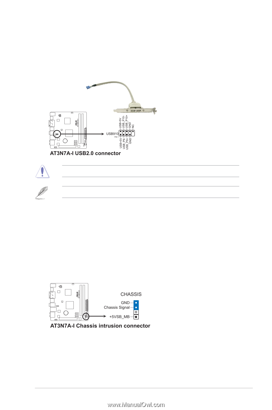
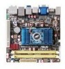
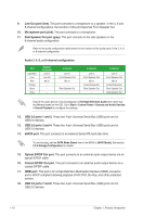
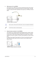
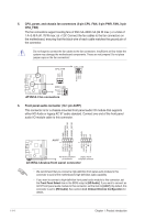
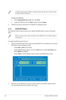
3. USB connector (10-1 pin USB910) This connector is for a USB 2.0 port. Connect the USB module cable to this connector, then install the module to a slot opening at the back of the system chassis. This USB connector complys with USB 2.0 specification that supports up to 480 Mbps connection speed. Never connect a 1394 cable to the USB connector. Doing so will damage the motherboard! The USB module cable is purchased separately. 4. Chassis intrusion connector (4-1 pin CHASSIS) This connector is for a chassis-mounted intrusion detection sensor or switch. Connect one end of the chassis intrusion sensor or switch cable to this connector. The chassis intrusion sensor or switch sends a high-level signal to this connector when a chassis component is removed or replaced. The signal is then generated as a chassis intrusion event. By default, the pin labeled "Chassis Signal" and "Ground" are shorted with a jumper cap. Remove the jumper caps only when you intend to use the chassis intrusion detection feature. ASUS AT3N7A-I 1-13
-
 1
1 -
2
-
3
-
4
-
5
-
6
-
7
-
8
-
9
-
10
-
11
-
12
-
13
-
14
-
15
-
16
-
 17
17 -
 18
18 -
 19
19 -
 20
20 -
 21
21 -
 22
22 -
 23
23 -
 24
24 -
 25
25 -
 26
26 -
 27
27 -
28
-
29
-
30
-
31
-
32
-
33
-
34
-
35
-
36
-
37
-
38
-
39
-
40
 |
 |