Asus BM6835 BM6635_BM6835_BP6335 User's Manual - Page 16
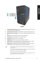
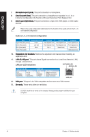
Microphone port pink., Line Out port lime., Line In port light blue., Expansion slot brackets.
 |
View all Asus BM6835 manuals
Add to My Manuals
Save this manual to your list of manuals |
Page 16 highlights
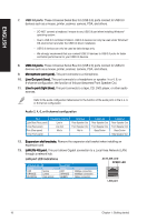
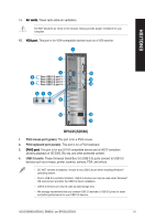
ENGLISH 7. ���M��ic�r�o�p�h��o�n�e��p�o�r�t �(p��in�k�)�. This port connects to a microphone. 8. ���L��in�e��O��u�t�p�o��rt��(l�im��e�)�. This port connects to a headphone or speaker. In a 4, 6, or 8-channel configuration, the function of this port becomes Front Speaker Out. 9 L�i�n�e��In��p�o��r�t�(�li�g�h�t��b�l�u�e�)�. This port connects to a tape, CD, DVD player, or other audio sources. Refer to the audio configuration table below for the function of the audio ports in the 2, 4, 6, or 8-channel configuration. Audio 2, 4, 6, or 8-channel configuration Port Light Blue (Rear panel) Lime (Rear panel) Pink (Rear panel) Lime (Front panel) Headset 2-channel Line In Line Out Mic In - 4-channel Rear Speaker Out Front Speaker Out Mic In - 6-channel Rear Speaker Out Front Speaker Out Bass/Center - 8-channel Rear Speaker Out Front Speaker Out Bass/Center Side Speaker Out 10. ��E��x�p�a�n�s��io�n��s�l�o�t�b��r�a�c�k�e�t�s�. Remove the expansion slot bracket when installing an expansion card. 11. ��L�A�N��(R��J�-4��5�)�p��o�r�t�. This port allows Gigabit connection to a Local Area Network (LAN) through a network hub. LAN port LED indications ACT/LINK LED SPEED LED Activity/Link LED Status Description OFF No link ORANGE Linked BLINKING Data activity Speed LED Status OFF ORANGE GREEN Description 10Mbps connection 100Mbps connection 1Gbps connection LAN port 12. � V�G��A��p�o�r�t�. This port is for VGA-compatible devices such as a VGA monitor. 13. ��A��ir��v�e�n�t�s�. These vents allow air ventilation. DO NOT block the air vents on the chassis. Always provide proper ventilation for your computer. 16 Chapter 1: Getting started
-
 1
1 -
2
-
3
-
4
-
5
-
6
-
7
-
8
-
9
-
10
-
 11
11 -
 12
12 -
 13
13 -
 14
14 -
 15
15 -
 16
16 -
 17
17 -
 18
18 -
 19
19 -
 20
20 -
 21
21 -
22
-
23
-
24
-
25
-
26
-
27
-
28
-
29
-
30
-
31
-
32
-
33
-
34
-
35
-
36
-
37
-
38
-
39
-
40
-
41
-
42
-
43
-
44
-
45
-
46
-
47
-
48
-
49
-
50
-
51
-
52
-
53
-
54
-
55
-
56
-
57
-
58
-
59
-
60
-
61
-
62
-
63
-
64
-
65
-
66
-
67
-
68
-
69
-
70
-
71
-
72
 |
 |
