Asus BM6835 BM6635_BM6835_BP6335 User's Manual - Page 20
Air vents., LAN port LED indications
 |
View all Asus BM6835 manuals
Add to My Manuals
Save this manual to your list of manuals |
Page 20 highlights
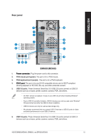
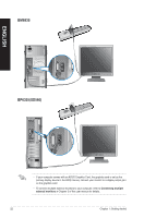
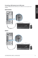
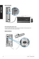
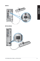
ENGLISH 5. ���U�S��B�2�.�0�p��o�rt�s�. These Universal Serial Bus 2.0 (USB 2.0) ports connect to USB 2.0 devices such as a mouse, printer, scanner, camera, PDA, and others. 6. ���M��ic�r�o�p�h��o�n�e��p�o�r�t �(p��in�k�)�. This port connects to a microphone. 7. ���L��in�e��O��u�t�p�o��rt��(l�im��e�)�. This port connects to a headphone or speaker. In a 4, 6, or 8-channel configuration, the function of this port becomes Front Speaker Out. 8 L�i�n�e��In��p�o��r�t�(�li�g�h�t��b�l�u�e�)�. This port connects to a tape, CD, DVD player, or other audio sources. Refer to the audio configuration table below for the function of the audio ports in the 2, 4, 6, or 8-channel configuration. Audio 2, 4, 6, or 8-channel configuration Port Light Blue (Rear panel) Lime (Rear panel) Pink (Rear panel) Lime (Front panel) Headset 2-channel Line In Line Out Mic In - 4-channel Rear Speaker Out Front Speaker Out Mic In - 6-channel Rear Speaker Out Front Speaker Out Bass/Center - 8-channel Rear Speaker Out Front Speaker Out Bass/Center Side Speaker Out 9. ���E�x�p��a�n�s�io��n�s�l�o�t�b�r�a�c�k�e�t�s�. Remove the expansion slot bracket when installing an expansion card. 10. Voltage selector. Use this switch to select the appropriate system input voltage according to the voltage supply in your area. If the voltage supply in your area is 100127V, set the switch to 115V. If the voltage supply in your area is 200-240V, set the switch to 230V.� Setting the switch to 115V in a 230V environment or 230V in a 115V environment will seriously damage the system! 11. Air vents. These vents allow air ventilation. DO NOT block the air vents on the chassis. Always provide proper ventilation for your computer. 12. ��P�o��w�e�r��c�o�n�n�e�c�t�o�r�. Plug the power cord to this connector. 13. ��L�A�N��(R�J�-�4��5�)�p��o�r�t�. This port allows Gigabit connection to a Local Area Network (LAN) through a network hub. LAN port LED indications ACT/LINK SPEED LED LED Activity/Link LED Status Description OFF No link ORANGE Linked BLINKING Data activity Speed LED Status OFF ORANGE GREEN Description 10Mbps connection 100Mbps connection 1Gbps connection LAN port 14. � V�G��A��p�o�r�t�. This port is for VGA-compatible devices such as a VGA monitor. 20 Chapter 1: Getting started
-
 1
1 -
2
-
3
-
4
-
5
-
6
-
7
-
8
-
9
-
10
-
11
-
12
-
13
-
14
-
 15
15 -
 16
16 -
 17
17 -
 18
18 -
 19
19 -
 20
20 -
 21
21 -
 22
22 -
 23
23 -
 24
24 -
 25
25 -
26
-
27
-
28
-
29
-
30
-
31
-
32
-
33
-
34
-
35
-
36
-
37
-
38
-
39
-
40
-
41
-
42
-
43
-
44
-
45
-
46
-
47
-
48
-
49
-
50
-
51
-
52
-
53
-
54
-
55
-
56
-
57
-
58
-
59
-
60
-
61
-
62
-
63
-
64
-
65
-
66
-
67
-
68
-
69
-
70
-
71
-
72
 |
 |
