Asus BP5270 User Manual - Page 13
Rear panel, Voltage selector
 |
View all Asus BP5270 manuals
Add to My Manuals
Save this manual to your list of manuals |
Page 13 highlights
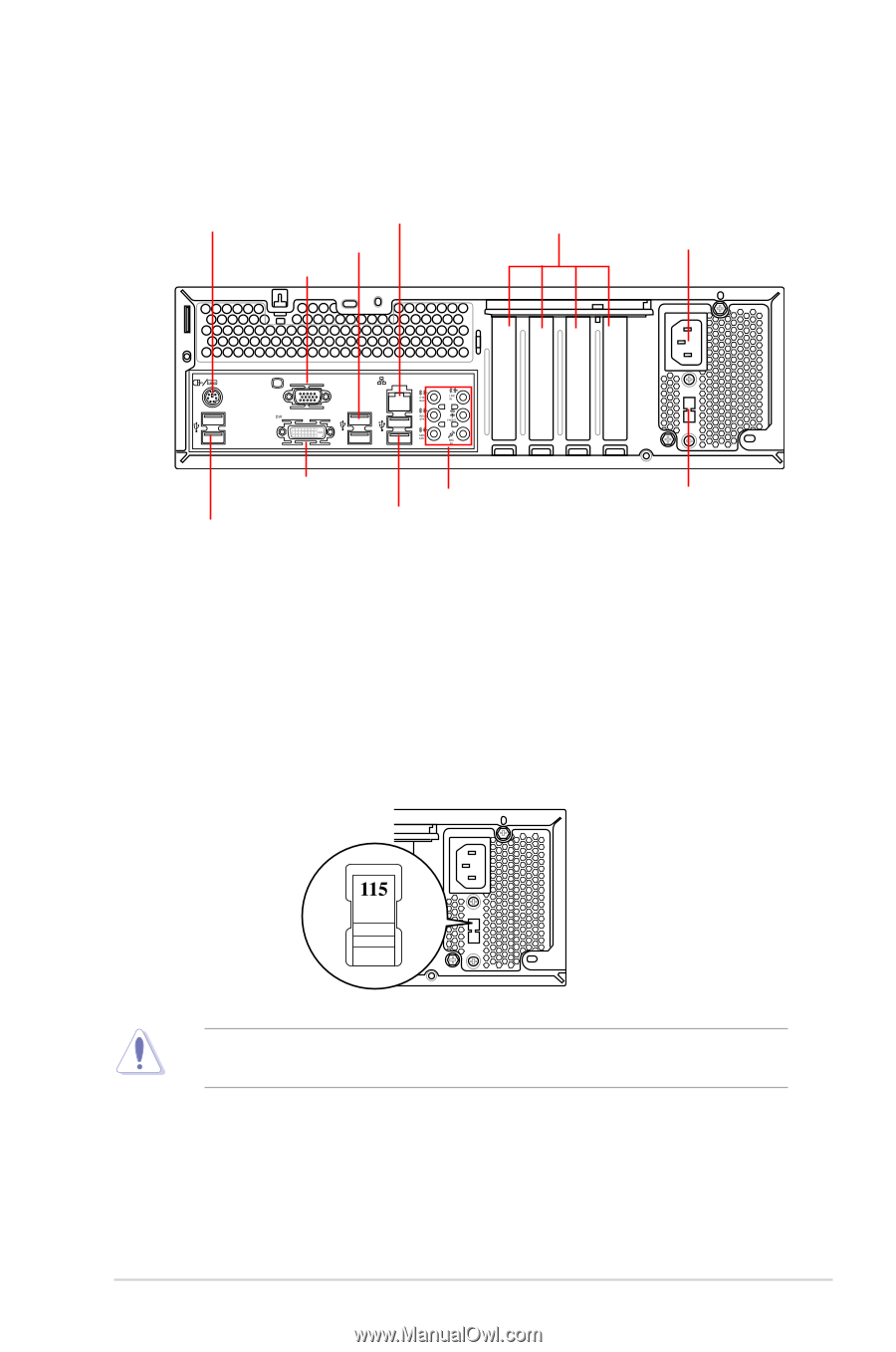
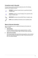
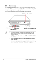
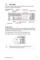
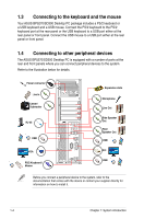
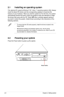
1.2 Rear panel The system rear panel includes the power connector and several I/O ports that allow you to conveniently connect devices. 1 x PS/2 Keyboard/Mouse Combo port 2 x USB 1 x RJ-45 2.0 ports port 1 x VGA port 4 x Expansion slots 1 x Power connector 15 1x DVI port 8-channel audio ports 2 x USB 2.0 ports 2 x USB 2.0 ports 1 x Voltage selector Voltage selector The system's power supply unit has a 115V / 230V voltage selector located below the power connector. Use this switch to select the appropriate system input voltage according to the voltage supply in your area. If the voltage supply in your area is 100-127V, set the switch to 115V. If the voltage supply in your area is 200-240V, set the switch to 230V. LINE IN 15 MIC IN Setting the switch to 115V in a 230V environment or 230V in a 115V environment will seriously damage the system! ASUS BP5270/SD300 1-3
-
 1
1 -
2
-
3
-
4
-
5
-
6
-
7
-
 8
8 -
 9
9 -
 10
10 -
 11
11 -
 12
12 -
 13
13 -
 14
14 -
 15
15 -
 16
16 -
 17
17 -
 18
18 -
19
-
20
-
21
-
22
-
23
-
24
-
25
-
26
-
27
-
28
-
29
-
30
-
31
-
32
-
33
 |
 |