Asus CG8565 User Manual - Page 14
Rear Speaker Out port black.
 |
View all Asus CG8565 manuals
Add to My Manuals
Save this manual to your list of manuals |
Page 14 highlights
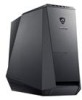
English 7. Side Speaker Out port (gray). This port connects to the side speakers in an 8-channel audio configuration. 8. ���R��e�a�r�S�p��e�a�k�e�r�O��u�t�p�o��rt��(b�l�a�c�k�)�. This port connects to the rear speakers in a 4, 6, and 8-channel audio configuration. 9. Center/Subwoofer port (orange). This port connects to the center/subwoofer speakers. 10. ��M��ic��ro��p�h�o�n�e��p�o��rt��(p�i�n�k�)�. This port connects to a microphone. 11. ��L��in��e�O��u�t��p�o�r�t�(�l�im��e�)�. This port connects to a headphone or speaker. In a 4, 6, or 8-channel configuration, the function of this port becomes Front Speaker Out. 12. ���L�i�n�e��In��p��o�r�t�(�l�ig��h�t��b�l�u�e�)�. This port connects to a tape, CD, DVD player, or other audio sources. Audio 2, 4, 6, or 8-channel configuration Port Light Blue Lime Pink Orange Black Gray Headset 2-channel Line In Line Out Mic In - - - 4-channel Line In Front Speaker Out Mic In - Rear Speaker Out - 6-channel Line In Front Speaker Out Mic In Center/Subwoofer Rear Speaker Out - 8-channel Line In Front Speaker Out Mic In Center/Subwoofer Rear Speaker Out Side Speaker Out 13. Air vents. These vents allow air ventilation. DO NOT block the air vents on the chassis. Always provide proper ventilation for your computer. 14. Power connector. Plug the power cord to this connector. 15. Power switch. Switch to turn ON/OFF the power supply to your computer. 16. Bluetooth module. Plug any bluetooth enabled device, such as cellular phones, for wireless data transfer. 17.���V�G�A��p�o��rt�. This port is for VGA-compatible devices such as a VGA monitor. 14 Chapter 1: Getting started
-
 1
1 -
2
-
3
-
4
-
5
-
6
-
7
-
8
-
 9
9 -
 10
10 -
 11
11 -
 12
12 -
 13
13 -
 14
14 -
 15
15 -
 16
16 -
 17
17 -
 18
18 -
 19
19 -
20
-
21
-
22
-
23
-
24
-
25
-
26
-
27
-
28
-
29
-
30
-
31
-
32
-
33
-
34
-
35
-
36
-
37
-
38
-
39
-
40
-
41
-
42
-
43
-
44
-
45
-
46
-
47
-
48
-
49
-
50
-
51
-
52
-
53
-
54
-
55
-
56
-
57
-
58
-
59
-
60
-
61
-
62
-
63
-
64
-
65
-
66
-
67
-
68
-
69
-
70
-
71
-
72
-
73
-
74
-
75
-
76
-
77
-
78
-
79
-
80
-
81
-
82
-
83
-
84
-
85
-
86
-
87
-
88
-
89
-
90
-
91
-
92
-
93
-
94
-
95
-
96
-
97
-
98
-
99
-
100
-
101
-
102
-
103
-
104
-
105
-
106
-
107
-
108
-
109
-
110
-
111
-
112
-
113
-
114
-
115
-
116
-
117
-
118
-
119
-
120
-
121
-
122
-
123
-
124
-
125
-
126
-
127
-
128
-
129
-
130
-
131
-
132
-
133
-
134
-
135
-
136
-
137
-
138
-
139
-
140
-
141
-
142
-
143
-
144
-
145
-
146
-
147
-
148
-
149
-
150
-
151
-
152
-
153
-
154
-
155
-
156
-
157
-
158
-
159
-
160
-
161
-
162
-
163
-
164
-
165
-
166
-
167
-
168
-
169
-
170
-
171
-
172
-
173
-
174
-
175
-
176
-
177
-
178
-
179
-
180
-
181
-
182
-
183
-
184
-
185
-
186
-
187
-
188
-
189
-
190
-
191
-
192
-
193
-
194
-
195
-
196
-
197
-
198
-
199
-
200
-
201
-
202
-
203
-
204
-
205
-
206
-
207
-
208
-
209
-
210
-
211
-
212
-
213
-
214
-
215
-
216
-
217
-
218
-
219
-
220
-
221
-
222
-
223
-
224
-
225
-
226
-
227
-
228
-
229
-
230
-
231
-
232
-
233
-
234
-
235
-
236
-
237
-
238
-
239
-
240
-
241
-
242
-
243
-
244
-
245
-
246
-
247
-
248
-
249
-
250
-
251
-
252
-
253
-
254
-
255
-
256
-
257
-
258
-
259
-
260
-
261
-
262
-
263
-
264
-
265
-
266
-
267
-
268
-
269
-
270
-
271
-
272
-
273
-
274
-
275
-
276
-
277
-
278
-
279
-
280
-
281
-
282
-
283
-
284
-
285
-
286
-
287
-
288
-
289
-
290
-
291
-
292
-
293
-
294
-
295
-
296
-
297
-
298
-
299
-
300
-
301
-
302
-
303
-
304
-
305
-
306
-
307
-
308
-
309
-
310
-
311
-
312
-
313
-
314
-
315
-
316
-
317
-
318
-
319
-
320
-
321
-
322
-
323
-
324
-
325
-
326
-
327
-
328
-
329
-
330
-
331
-
332
-
333
-
334
-
335
-
336
-
337
-
338
-
339
-
340
-
341
-
342
-
343
-
344
-
345
-
346
-
347
-
348
-
349
-
350
-
351
-
352
-
353
-
354
-
355
-
356
-
357
-
358
-
359
-
360
-
361
-
362
-
363
-
364
-
365
-
366
-
367
-
368
-
369
-
370
-
371
-
372
-
373
-
374
-
375
-
376
-
377
-
378
-
379
-
380
-
381
-
382
-
383
-
384
-
385
-
386
-
387
-
388
-
389
-
390
-
391
-
392
-
393
-
394
-
395
-
396
-
397
-
398
-
399
-
400
-
401
-
402
-
403
-
404
-
405
-
406
-
407
-
408
-
409
-
410
 |
 |