Asus E45M1-I DELUXE User Manual - Page 12
Motherboard overview - ram
 |
View all Asus E45M1-I DELUXE manuals
Add to My Manuals
Save this manual to your list of manuals |
Page 12 highlights
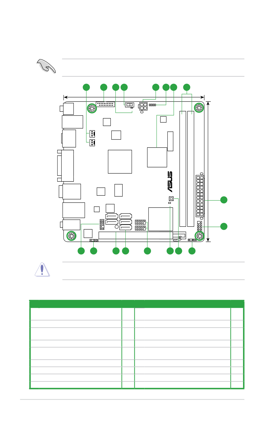
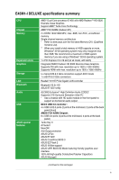
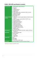
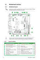
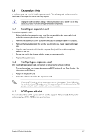
1.2 1.2.1 Motherboard overview Motherboard layout Ensure that you install the motherboard into the chassis in the correct orientation. The edge with external ports goes to the rear part of the chassis. 1 2 34 5 67 8 17cm(6.7in) ANTENNA _PORT KB_USB34 USB3_34 TURBO_KEY_II O2LED2 NEC USB3.0 CHA_FAN Super I/O CLRTC ATX12V EPU CPU_FAN AMD® Hudson M1 AMD® E-450 Processor with RadeonTM HD 6320 Graphics HDMI SPDIF_O2 Lithium Cell CMOS Power E45M1-I DELUXE DDR3 DIMM1 (64bit, 240-pin module) DDR3 DIMM2 (64bit, 240-pin module) EATXPWR 17cm(6.7in) DVI ICS 9LRPS483 ESATA6G _USB12 _BT NEC USB3.0 MemOK! 5 LAN1_USB3_12 RTL 8111E 32Mb BIOS SATA6G_2 SATA6G_4 SATA6G_1 SATA6G_3 SATA6G_5 USB78 USB56 DRAM_LED WLAN F_PANEL AUDIO ALC 892 AAFP SB_PWR SPDIF_OUT PCIEX16 9 CHASSIS 17 16 15 14 13 12 11 10 Place four screws into the holes indicated by circles to secure the motherboard to the chassis. DO NOT overtighten the screws! Doing so can damage the motherboard. 1.2.2 Layout contents Connectors/Jumpers/Slots/LED 1. CPU and chassis fan connectors (3-pin CPU_FAN, 3-pin CHA_FAN) 2. USB 3.0 connector (20-1 pin USB3_34) 3. Turbo Key II LED (O2LED2) Page Connectors/Jumpers/Slots/LED Page 1-12 10. Chassis intrusion connector (4-1 pin CHASSIS) 1-14 1-15 11. MemOK! switch 1-17 1-18 12. DARM LED (DRAM_LED) 1-18 4. Turbo Key II switch 1-16 13. USB 2.0 connectors (10-1 pin USB56, USB78) 1-15 5. ATX power connectors (24-pin EATXPWR, 1-11 14. Serial ATA 6.0Gb/s connectors (7-pin 1-13 4-pin ATX12V) SATA6G_1~5) 6. Clear RTC RAM (3-pin CLRTC) 1-8 15. Standby power LED (SB_PWR) 1-18 7. AMD® Zacate™ 18W processor 1-3 16. Digital audio connector (4-1 pin SPDIF_OUT) 1-12 8. DDR3 DIMM slots 1-3 17. Front panel audio connector (10-1 pin AAFP) 1-13 9. System panel connector (10-1 pin F_PANEL) 1-14 1-2 ASUS E45M1-I DELUXE
-
 1
1 -
2
-
3
-
4
-
5
-
6
-
 7
7 -
 8
8 -
 9
9 -
 10
10 -
 11
11 -
 12
12 -
 13
13 -
 14
14 -
 15
15 -
 16
16 -
 17
17 -
18
-
19
-
20
-
21
-
22
-
23
-
24
-
25
-
26
-
27
-
28
-
29
-
30
-
31
-
32
-
33
-
34
-
35
-
36
-
37
-
38
-
39
-
40
-
41
-
42
-
43
-
44
-
45
-
46
-
47
-
48
-
49
-
50
-
51
-
52
-
53
-
54
-
55
-
56
 |
 |