Asus E45M1-I DELUXE User Manual - Page 23
E45M1-I DELUXE SATA 6.0Gb/s connectors - e35m1 i deluxe motherboard
 |
View all Asus E45M1-I DELUXE manuals
Add to My Manuals
Save this manual to your list of manuals |
Page 23 highlights
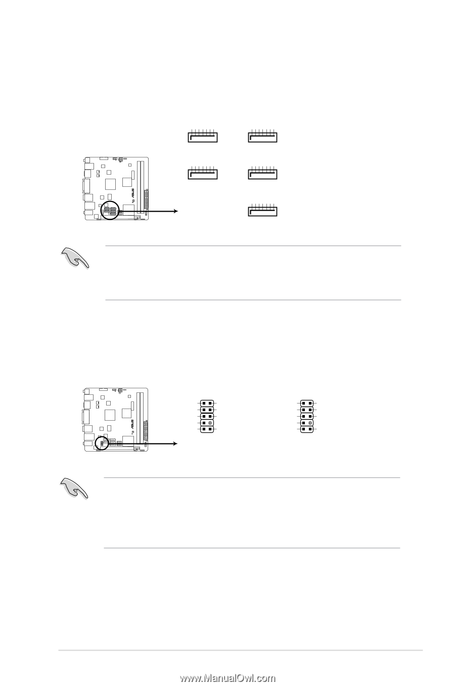
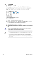
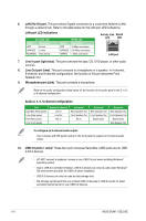
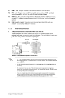
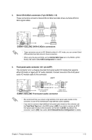
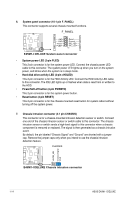
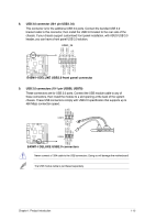
4. Serial ATA 6.0Gb/s connectors (7-pin SATA6G_1~5) These connectors connect to Serial ATA 6.0 Gb/s hard disk drives via Serial ATA 6.0 Gb/s signal cables. GND RSATA_RXN1 RSATA_RXP1 GND RSATA_TXN1 RSATA_TXP1 GND GND RSATA_RXN2 RSATA_RXP2 GND RSATA_TXN2 RSATA_TXP2 GND SATA6G_2 SATA6G_1 GND RSATA_RXN3 RSATA_RXP3 GND RSATA_TXN3 RSATA_TXP3 GND GND RSATA_RXN4 RSATA_RXP4 GND RSATA_TXN4 RSATA_TXP4 GND E35M1-I DELUXE SATA6G_4 SATA6G_3 GND RSATA_RXN5 RSATA_RXP5 GND RSATA_TXN5 RSATA_TXP5 GND SATA6G_5 E45M1-I DELUXE SATA 6.0Gb/s connectors • These connectors are set to [IDE Mode] by default. In IDE mode, you can connect Serial ATA boot/data hard disk drives to these connectors. • When using hot-plug and NCQ, set the OnChip SATA Type item in the BIOS to [AHCI Mode]. See section 2.5.2 SATA Configuration for details. 5. Front panel audio connector (10-1 pin AAFP) This connector is for a chassis-mounted front panel audio I/O module that supports either HD Audio or legacy AC`97 audio standard. Connect one end of the front panel audio I/O module cable to this connector. AAFP E35M1-I DELUXE PIN 1 PORT1 L PORT1 R PORT2 R SENSE_SEND PORT2 L GND PRESENCE# SENSE1_RETUR SENSE2_RETUR PIN 1 MIC2 MICPWR Line out_R NC Line out_L AGND NC NC NC HD-audio-compliant pin definition Legacy AC'97 compliant definition E45M1-I DELUXE Front panel audio connector • We recommend that you connect a high-definition front panel audio module to this connector to avail of the motherboard's high-definition audio capability. • If you want to connect a high-definition front panel audio module to this connector, set the Front Panel Type item in the BIOS setup to [HD]. If you want to connect an AC'97 front panel audio module to this connector, set the item to [AC97]. By default, this connector is set to [HD]. See section 2.5.5 Onboard Devices Configuration for details. Chapter 1: Product introduction 1-13
-
 1
1 -
2
-
3
-
4
-
5
-
6
-
7
-
8
-
9
-
10
-
11
-
12
-
13
-
14
-
15
-
16
-
17
-
 18
18 -
 19
19 -
 20
20 -
 21
21 -
 22
22 -
 23
23 -
 24
24 -
 25
25 -
 26
26 -
 27
27 -
 28
28 -
29
-
30
-
31
-
32
-
33
-
34
-
35
-
36
-
37
-
38
-
39
-
40
-
41
-
42
-
43
-
44
-
45
-
46
-
47
-
48
-
49
-
50
-
51
-
52
-
53
-
54
-
55
-
56
 |
 |