Asus E500-PIB CUSL2-M User Manual - Page 41
ASUS CUSL2-M User's Manual, ATX Power Supply Connector, pin block ATXPWR, Standard and Consumer
 |
View all Asus E500-PIB manuals
Add to My Manuals
Save this manual to your list of manuals |
Page 41 highlights
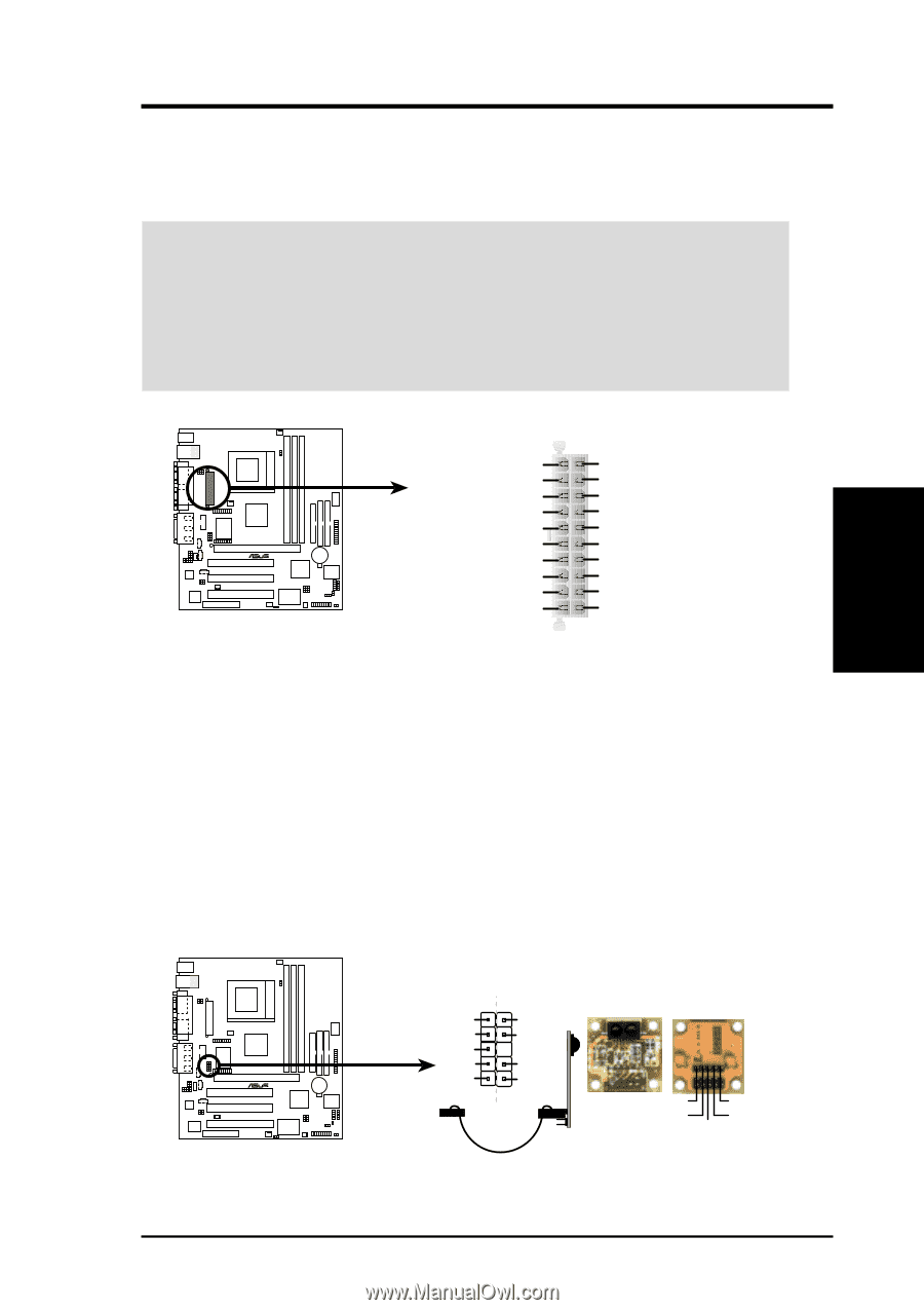
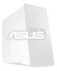
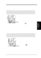
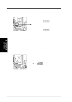
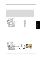
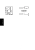
3. HARDWARE SETUP 25) ATX Power Supply Connector (20-pin block ATXPWR) This connector connects to an ATX power supply. The plug from the power supply will only insert in one orientation because of the different hole sizes. Find the proper orientation and push down firmly making sure that the pins are aligned. IMPORTANT: Make sure that your ATX power supply (minimum recommended wattage: 200 watts; 235W for a fully-configured system) can supply at least 20 amperes on the +5-volt lead and at least 10mA (750mA recommended) on the +5volt standby lead (+5VSB). Your system may become unstable/unreliable and may experience difficulty in powering up if your power supply is inadequate. For WakeOn-LAN support, your ATX power supply must supply at least 750mA +5VSB. 3. H/W SETUP Connectors CUSL2-M ® +3.3 Volts -12.0 Volts Ground Power Supply On Ground Ground Ground -5.0 Volts +5.0 Volts +5.0 Volts CUSL2-M ATX Power Connector +3.3 Volts +3.3 Volts Ground +5.0 Volts Ground +5.0 Volts Ground Power Good +5V Standby +12.0 Volts 26) Standard and Consumer Infrared Module Connector (10-1 pin IR_CON) This connector supports an optional wireless transmitting and receiving infrared module. This module mounts to a small opening on system cases that support this feature. You must also configure the setting through UART2 Use Infrared (see 4.4.2 I/O Device Configuration) to select whether UART2 is directed for use with COM2 or IrDA. Use the five pins as shown in Back View and connect a ribbon cable from the module to the motherboard's SIR connector according to the pin definitions. An optional consumer infrared (CIR) set connects to the CIR and SIR connectors simultaneously for both wireless transmitting and remote control functions through one external infrared module. CUSL2-M ® SIR CIR IRTX CIR+5V GND CIRRX IRRX (NC) GND +5V (NC) CUSL2-M Infrared Module Connector Standard Infrared (SIR) Front View Back View IRTX +5V GND (NC) IRRX ASUS CUSL2-M User's Manual 41
-
 1
1 -
2
-
3
-
4
-
5
-
6
-
7
-
8
-
9
-
10
-
11
-
12
-
13
-
14
-
15
-
16
-
17
-
18
-
19
-
20
-
21
-
22
-
23
-
24
-
25
-
26
-
27
-
28
-
29
-
30
-
31
-
32
-
33
-
34
-
35
-
 36
36 -
 37
37 -
 38
38 -
 39
39 -
 40
40 -
 41
41 -
 42
42 -
 43
43 -
 44
44 -
 45
45 -
 46
46 -
47
-
48
-
49
-
50
-
51
-
52
-
53
-
54
-
55
-
56
-
57
-
58
-
59
-
60
-
61
-
62
-
63
-
64
-
65
-
66
-
67
-
68
-
69
-
70
-
71
-
72
-
73
-
74
-
75
-
76
-
77
-
78
-
79
-
80
-
81
-
82
-
83
-
84
-
85
-
86
-
87
-
88
-
89
-
90
-
91
-
92
-
93
-
94
-
95
-
96
-
97
-
98
-
99
-
100
-
101
-
102
-
103
-
104
-
105
-
106
-
107
-
108
-
109
-
110
-
111
-
112
-
113
-
114
-
115
-
116
-
117
-
118
-
119
-
120
-
121
-
122
-
123
-
124
-
125
-
126
-
127
-
128
 |
 |