Asus EX-B150M-V3 Users manual English - Page 12
IRQ assignments for this motherboard, Digital audio connector 4-1 pin SPDIF_OUT
 |
View all Asus EX-B150M-V3 manuals
Add to My Manuals
Save this manual to your list of manuals |
Page 12 highlights
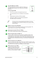
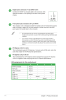
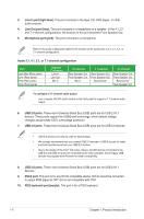
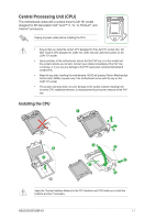
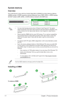
+5V SPDIFOUT GND Digital audio connector (4-1 pin SPDIF_OUT) Connect the S/PDIF Out module cable to this connector, then install the module to a slot opening at the back of the system chassis. PIN 1 SPDIF_OUT Front panel audio connector (10-1 pin AAFP) This connector is for a chassis-mounted front panel audio I/O module that supports either HD Audio or legacy AC`97 audio standard. Connect one end of the front panel audio I/O module cable to this connector. • We recommend that you connect a high-definition front panel audio module to this connector to avail of the motherboard's high-definition audio capability. • If you want to connect a high-definition front panel audio module to this connector, set the Front Panel Type item in the BIOS setup to [HD Audio]. If you want to connect an AC'97 front panel audio module to this connector, set the item to [AC97]. By default, this connector is set to [HD Audio]. PCI Express 3.0/2.0 x1 slots This motherboard supports PCI Express x1 network cards, SCSI cards, and other cards that comply with the PCI Express specifications. PCI Express 3.0/2.0 x16 slot This motherboard has a PCI Express 3.0/2.0 x16 slot that supports PCI Express 3.0/2.0 x16 graphic cards complying with the PCI Express specifications. IRQ assignments for this motherboard SATA Controller A B shared - HD Audio XHCI Controller LAN PCIE x16 PCIE x1_1 PCIE x1_2 shared shared - shared - - - - - - shared - C - - - - - - shared D - - - shared - - - 1-4 Chapter 1: Product introduction
-
 1
1 -
2
-
3
-
4
-
5
-
6
-
 7
7 -
 8
8 -
 9
9 -
 10
10 -
 11
11 -
 12
12 -
 13
13 -
 14
14 -
 15
15 -
 16
16 -
 17
17 -
18
-
19
-
20
-
21
-
22
-
23
-
24
-
25
-
26
 |
 |
