Asus EX-B150M-V3 Users manual English - Page 13
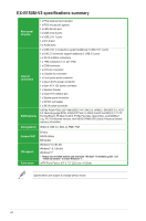
Rear panel connectors, Activity/Link LED, Speed LED, Status, Description
 |
View all Asus EX-B150M-V3 manuals
Add to My Manuals
Save this manual to your list of manuals |
Page 13 highlights
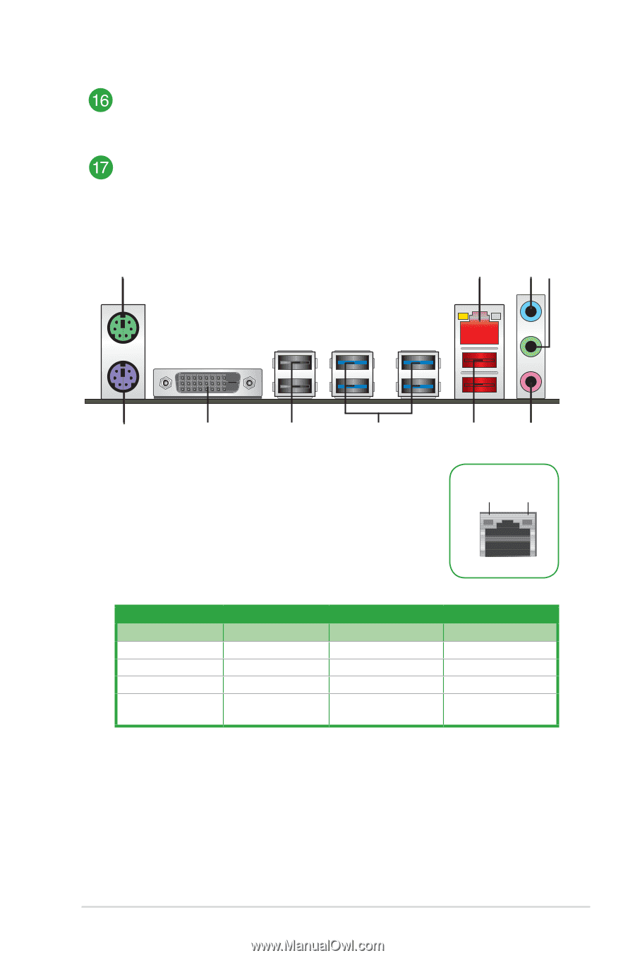
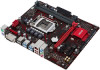
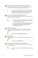
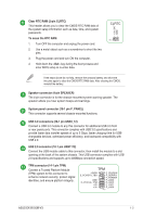
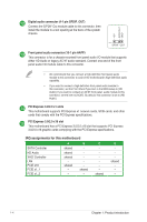
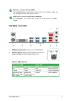
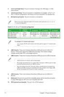
Serial port connector (10-1 pin COM) Connect the serial port module cable to this connector, then install the module to a slot opening at the back of the system chassis. SATA power connector (15-pin SATA_PWRCON) Connect the SATA power cable to this connector to provide power to your SATA device. Rear panel connectors 1 2 34 10 9 8 7 1. PS/2 mouse port (green). This port is for a PS/2 mouse. 2. LAN (RJ-45) port. This port allows Gigabit connection to a Local Area Network (LAN) through a network hub. 6 5 Activity Link Speed LED LED LAN port LED indications Activity/Link LED Status Off Orange Orange (Blinking) Orange (Blinking then steady) Description No link Linked Data activity Ready to wake up from S5 mode Speed LED Status OFF ORANGE GREEN _ LAN port Description 10Mbps connection 100Mbps connection 1Gbps connection _ ASUS EX-B150M-V3 1-5
-
 1
1 -
2
-
3
-
4
-
5
-
6
-
7
-
 8
8 -
 9
9 -
 10
10 -
 11
11 -
 12
12 -
 13
13 -
 14
14 -
 15
15 -
 16
16 -
 17
17 -
 18
18 -
19
-
20
-
21
-
22
-
23
-
24
-
25
-
26
 |
 |