Asus EX-B250-V7 User Guide - Page 11
B250 Serial ATA 6.0Gb/s connectors 7-pin SATA6G_1~6, Clear RTC RAM 2-pin CLRTC
 |
View all Asus EX-B250-V7 manuals
Add to My Manuals
Save this manual to your list of manuals |
Page 11 highlights
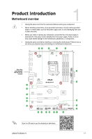
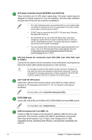
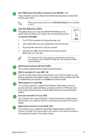
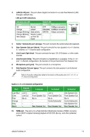
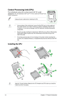
Intel® B250 Serial ATA 6.0Gb/s connectors (7-pin SATA6G_1~6) These connectors connect to Serial ATA 6.0 Gb/s hard disk drives via Serial ATA 6.0 Gb/s signal cables. When using hot-plug and NCQ, set the SATA Mode Selection item in the BIOS to [AHCI]. Clear RTC RAM (2-pin CLRTC) This header allows you to clear the CMOS RTC RAM data of the system setup information such as date, time, and system passwords. To erase the RTC RAM: 1. Turn OFF the computer and unplug the power cord. 2. Use a metal object such as a screwdriver to short the two pins. 3. Plug the power cord and turn ON the computer. 4. Hold down the key during the boot process and enter BIOS setup to re-enter data. +3V_BAT GND CLRTC PIN 1 If the steps above do not help, remove the onboard battery and short the two pins again to clear the CMOS RTC RAM data. After clearing the CMOS, reinstall the battery. System panel connector (20-5 pin PANEL) This connector supports several chassis-mounted functions. USB 2.0 connector (10-1 pin USB1112) Connect the USB module cable to this connector, then install the module to a slot opening at the back of the system chassis. This USB connector complies with USB 2.0 specifications and supports up to 480Mbps connection speed. TPM connector (14-1 pin TPM) This connector supports a Trusted Platform Module (TPM) system, which can securely store keys, digital certificates, passwords and data. A TPM system also helps enhance network security, protects digital identities, and ensures platform integrity. Serial port connector (10-1 pin COM) This connector is for a serial (COM) port. Connect the serial port module cable to this connector, then install the module to a slot opening at the back of the system chassis Digital audio connector (4-1 pin SPDIF_OUT) This connector is for an additional Sony/Philips Digital Interface (S/PDIF) port. Connect the S/PDIF Out module cable to this connector, then install the module to a slot opening at the back of the system chassis. ASUS EX-B250-V7 1-3
-
 1
1 -
2
-
3
-
4
-
5
-
 6
6 -
 7
7 -
 8
8 -
 9
9 -
 10
10 -
 11
11 -
 12
12 -
 13
13 -
 14
14 -
 15
15 -
 16
16 -
17
-
18
-
19
-
20
-
21
-
22
-
23
-
24
-
25
-
26
-
27
-
28
-
29
-
30
 |
 |