Asus EX-B250-V7 User Guide - Page 9
Product introduction, Motherboard overview - v7 intel socket
 |
View all Asus EX-B250-V7 manuals
Add to My Manuals
Save this manual to your list of manuals |
Page 9 highlights
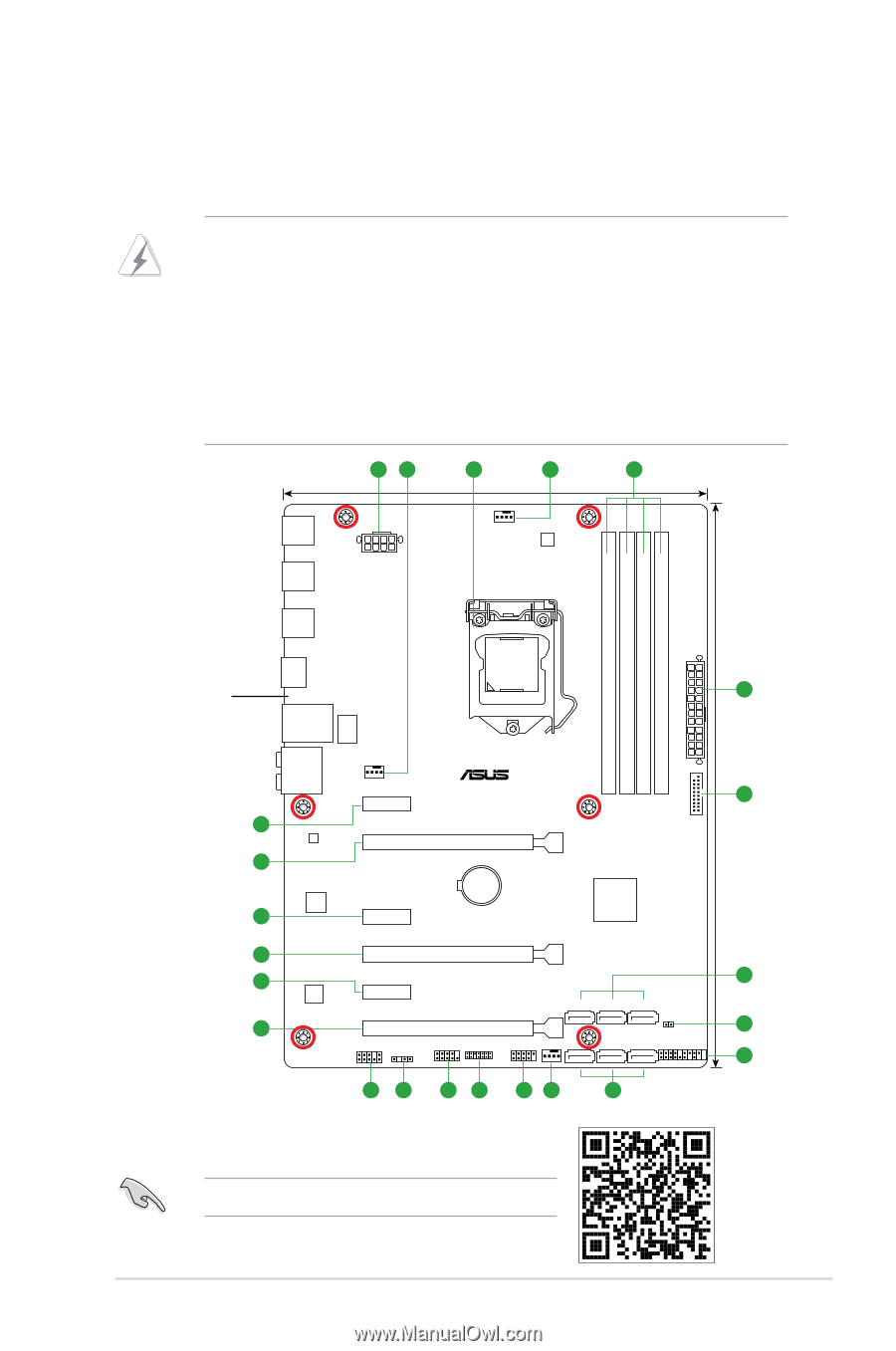
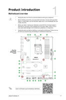
Product introduction Motherboard overview 1 • Unplug the power cord from the wall socket before touching any component. • Before handling components, use a grounded wrist strap or touch a safely grounded object or a metal object, such as the power supply case, to avoid damaging them due to static electricity. • Before you install or remove any component, ensure that the ATX power supply is switched off or the power cord is detached from the power supply. Failure to do so may cause severe damage to the motherboard, peripherals, or components. • Unplug the power cord before installing or removing the motherboard. Failure to do so can cause you physical injury and damage to motherboard components. 12 3 2 4 22.9cm(9.0in) USB910 USB3_56 EATX12V CPU_FAN DIGI +VRM EPU DDR4 DIMM_A1 (64bit, 288-pin module) DDR4 DIMM_A2 (64bit, 288-pin module) DDR4 DIMM_B1 (64bit, 288-pin module) DDR4 DIMM_B2 (64bit, 288-pin module) EATXPWR 30.5cm(12in) USB3_34 LGA1151 Place this HDMI side towards 1 the rear of the chassis LAN_USB78 LANGuard AUDIO USB3_12 CHA_FAN PCIEX1_1 EX-B250-V7 5 15 14 Intel® I219-V PCIEX16_1 Super I/O 15 PCIEX1_2 BATTERY Intel® B250 14 PCIEX16_2 15 ALC 887 14 PCIEX1_3 PCIEX16_3 6 SATA6G_6 SATA6G_4 SATA6G_2 CLRTC 7 AAFP SPDIF_OUT COM TPM USB1112 W_PUMP+ 8 SATA6G_5 SATA6G_3 SATA6G_1 PANEL 13 12 11 10 92 6 Scan the QR code to get the detailed pin definitions. ASUS EX-B250-V7 1-1
-
 1
1 -
2
-
3
-
 4
4 -
 5
5 -
 6
6 -
 7
7 -
 8
8 -
 9
9 -
 10
10 -
 11
11 -
 12
12 -
 13
13 -
 14
14 -
15
-
16
-
17
-
18
-
19
-
20
-
21
-
22
-
23
-
24
-
25
-
26
-
27
-
28
-
29
-
30
 |
 |