Asus EX-H610M-V3 D4-CSM EX-H610M-V3 D4 Users Manual English - Page 9
Product Introduction, 1.1 Before you proceed, 1.2 Motherboard overview
 |
View all Asus EX-H610M-V3 D4-CSM manuals
Add to My Manuals
Save this manual to your list of manuals |
Page 9 highlights
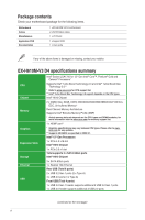
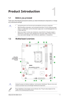
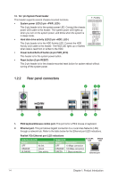
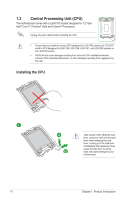
Product Introduction 1 1.1 Before you proceed Take note of the following precautions before you install motherboard components or change any motherboard settings. • Unplug the power cord from the wall socket before touching any component. • Before handling components, use a grounded wrist strap or touch a safely grounded object or a metal object, such as the power supply case, to avoid damaging them due to static electricity. • Before you install or remove any component, ensure that the ATX power supply is switched off or the power cord is detached from the power supply. Failure to do so may cause severe damage to the motherboard, peripherals, or components. 1.2 Motherboard overview 5 1 20.3cm(8.0in) 42 KBMS_USB_56 ATX_12V DIGI+ VRM CPU_FAN HDMI ATX_PWR DDR4 DIMM_A1 (64bit, 288-pin module) DDR4 DIMM_B1 (64bit, 288-pin module) 23.4cm(9.2in) Place this 5 side towards the rear of the LGA1700 chassis U32G1_34 U32G1_12 4 7 LAN_USB_78 CHA_FAN AUDIO Ethernet PCIEX16(G4) BATTERY 3 Audio Codec Super I/O COM_DEBUG PCIEX1(G3) Intel® H610 AAFP 10 USB_914 CLRTC SATA6G_1 SATA6G_2 SATA6G_3 98 6 128Mb BIOS SPEAKER F_PANEL 12 11 Unplug the power cord before installing or removing the motherboard. Failure to do so can cause you physical injury and damage motherboard components. The pin definitions in this chapter are for reference only. The pin names depend on the location of the header/jumper/connector. ASUS EX-H610M-V3 D4 1-1
-
 1
1 -
2
-
3
-
 4
4 -
 5
5 -
 6
6 -
 7
7 -
 8
8 -
 9
9 -
 10
10 -
 11
11 -
 12
12 -
 13
13 -
 14
14 -
15
-
16
-
17
-
18
-
19
-
20
-
21
-
22
-
23
-
24
-
25
-
26
-
27
-
28
-
29
-
30
-
31
-
32
-
33
-
34
 |
 |
