Asus F1A55 User Manual - Page 30
Connectors
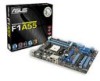 |
View all Asus F1A55 manuals
Add to My Manuals
Save this manual to your list of manuals |
Page 30 highlights
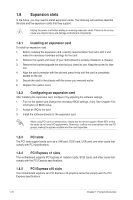
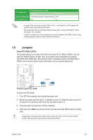
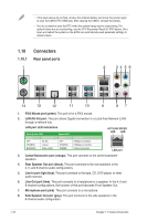
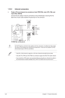
• If the steps above do not help, remove the onboard battery and move the jumper again to clear the CMOS RTC RAM data. After clearing the CMOS, reinstall the battery. • You do not need to clear the RTC when the system hangs due to overclocking. For system failure due to overclocking, use the CPU Parameter Recall (C.P.R) feature. Shut down and reboot the system so the BIOS can automatically reset parameter settings to default values. 1.10 1.10.1 1 Connectors Rear panel ports 2 34 56 14 13 12 11 10 9 87 1. PS/2 Mouse port (green). This port is for a PS/2 mouse. 2. LAN (RJ-45) port. This port allows Gigabit connection to a Local Area Network (LAN) through a network hub. LAN port LED indications Activity/Link LED Status Description OFF No link ORANGE Linked BLINKING Data activity Speed LED Status OFF ORANGE GREEN Description 10Mbps connection 100Mbps connection 1Gbps connection ACT/LINK SPEED LED LED LAN port 3. Center/Subwoofer port (orange). This port connects to the center/subwoofer speakers. 4. Rear Speaker Out port (black). This port connects to the rear speakers in the 4, 6, and 8-channel audio configurations. 5. Line In port (light blue). This port connects to the tape, CD, DVD player, or other audio sources. 6. Line Out port (lime). This port connects to a headphone or a speaker. In the 4, 6 and 8-channel configurations, the function of this port becomes Front Speaker Out. 7. Microphone port (pink). This port connects to a microphone. 8. Side Speaker Out port (gray). This port connects to the side speakers in the 8-channel audio configuration. 1-18 Chapter 1: Product introduction
-
 1
1 -
2
-
3
-
4
-
5
-
6
-
7
-
8
-
9
-
10
-
11
-
12
-
13
-
14
-
15
-
16
-
17
-
18
-
19
-
20
-
21
-
22
-
23
-
24
-
 25
25 -
 26
26 -
 27
27 -
 28
28 -
 29
29 -
 30
30 -
 31
31 -
 32
32 -
 33
33 -
 34
34 -
 35
35 -
36
-
37
-
38
-
39
-
40
-
41
-
42
-
43
-
44
-
45
-
46
-
47
-
48
-
49
-
50
-
51
-
52
-
53
-
54
-
55
-
56
-
57
-
58
-
59
-
60
-
61
-
62
-
63
-
64
-
65
-
66
-
67
-
68
-
69
-
70
 |
 |
