Asus H81M-F PLUS User Guide - Page 25
H81M-F PLUS TPM connector, System panel connector 10-1 pin F_PANEL, TPM connector 20-1 pin TPM
 |
View all Asus H81M-F PLUS manuals
Add to My Manuals
Save this manual to your list of manuals |
Page 25 highlights
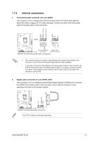
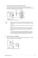
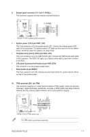
9. System panel connector (10-1 pin F_PANEL) This connector supports several chassis-mounted functions. +PWR LED PWR BTN +HDD_LED RESET H81M-F PLUS F_PANEL GND PWR PWR_LEDPWR_LED+ (NC) HWRST# Ground HDD_LEDHDD_LED+ PIN 1 H81M-F PLUS System panel connector • System power LED (2-pin PWR_LED) This 2-pin connector is for the system power LED. Connect the chassis power LED cable to this connector. The system power LED lights up when you turn on the system power, and blinks when the system is in sleep mode. • Hard disk drive activity LED (2-pin HDD_LED) This 2-pin connector is for the HDD Activity LED. Connect the HDD Activity LED cable to this connector. The HDD LED lights up or flashes when data is read from or written to the HDD. • ATX power button/soft-off button (2-pin PWR_BTN) This connector is for the system power button. • Reset button (2-pin RESET) This 2-pin connector is for the chassis-mounted reset button for system reboot without turning off the system power. 10. TPM connector (20-1 pin TPM) This connector supports a Trusted Platform Module (TPM) system, which can securely store keys, digital certificates, passwords, and data. A TPM system also helps enhance network security, protects digital identities, and ensures platform integrity. LPCPD# GND +3VSB NC LAD0 +3V LAD3 PCIRST# LFRAME# LCLK H81M-F PLUS TPM PIN 1 NC CLKRUN# SERIRQ NC GND LAD1 LAD2 NC GND H81M-F PLUS TPM connector The TPM module is purchased separately. ASUS H81M-F PLUS 1-17
-
 1
1 -
2
-
3
-
4
-
5
-
6
-
7
-
8
-
9
-
10
-
11
-
12
-
13
-
14
-
15
-
16
-
17
-
18
-
19
-
 20
20 -
 21
21 -
 22
22 -
 23
23 -
 24
24 -
 25
25 -
 26
26 -
 27
27 -
 28
28 -
 29
29 -
 30
30 -
31
-
32
-
33
-
34
-
35
-
36
-
37
-
38
-
39
-
40
-
41
-
42
-
43
-
44
-
45
-
46
 |
 |
