Asus H81M-V PLUS User Guide - Page 25
H81M-V PLUS Serial port connector
 |
View all Asus H81M-V PLUS manuals
Add to My Manuals
Save this manual to your list of manuals |
Page 25 highlights
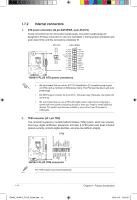
RXD DTR DSR CTS DCD TXD GND RTS RI 7. Serial port connector (10-1 pin COM) This connector is for a serial (COM) port. Connect the serial port module cable to this connector, then install the module to a slot opening at the back of the system chassis. COM PIN 1 H81M-V PLUS H81M-V PLUS Serial port connector The COM module is purchased separately. 8. Speaker connector (4-pin SPEAKER) The 4-pin connector is for the chassis-mounted system warning speaker. The speaker allows you hear system beeps and warnings. SPEAKER H81M-V PLUS PIN 1 H81M-V PLUS Speaker connector +5V GND GND Speaker Out ASUS H81M-V PLUS E9408_H81M-V_PLUS_Guide.indb 17 1-17 2015/1/19 15:50:59
-
 1
1 -
2
-
3
-
4
-
5
-
6
-
7
-
8
-
9
-
10
-
11
-
12
-
13
-
14
-
15
-
16
-
17
-
18
-
19
-
 20
20 -
 21
21 -
 22
22 -
 23
23 -
 24
24 -
 25
25 -
 26
26 -
 27
27 -
 28
28 -
 29
29 -
 30
30 -
31
-
32
-
33
-
34
-
35
-
36
-
37
-
38
-
39
-
40
-
41
-
42
-
43
-
44
 |
 |

ASUS H81M-V PLUS
1-17
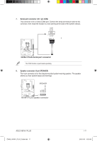
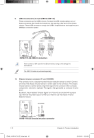
8.
Speaker connector (4-pin SPEAKER)
The 4-pin connector is for the chassis-mounted system warning speaker. The speaker
allows you hear system beeps and warnings.
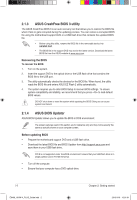
7.
Serial port connector (10-1 pin COM)
This connector is for a serial (COM) port. Connect the serial port module cable to this
connector, then install the module to a slot opening at the back of the system chassis.
The COM module is purchased separately.
H81M-V PLUS
H81M-V PLUS Serial port connector
PIN 1
COM
DCD
TXD
GND
RTS
RI
RXD
DTR
DSR
CTS
H81M-V PLUS
H81M-V PLUS Speaker connector
+5V
GND
GND
Speaker Out
SPEAKER
PIN 1
E9408_H81M-V_PLUS_Guide.indb
17
2015/1/19
15:50:59