Asus H81M-V PLUS User Guide - Page 27
H81M-V PLUS System panel connector
 |
View all Asus H81M-V PLUS manuals
Add to My Manuals
Save this manual to your list of manuals |
Page 27 highlights
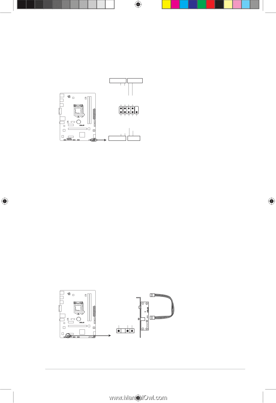
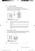
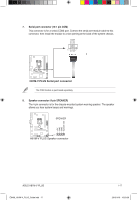
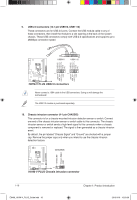
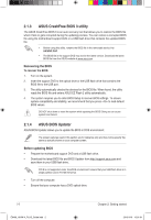
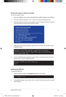
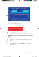
PWR_LED+ PWR_LEDPWR GND HDD_LED+ HDD_LED- Ground HWRST# (NC) 11. System panel connector (10-1 pin PANEL) This connector supports several chassis-mounted functions. F_PANEL +PWR LED PWR_BTN PIN 1 H81M-V PLUS +HDD_LED- RESET H81M-V PLUS System panel connector • System power LED (2-pin +PWR_LED-) This 2-pin connector is for the system power LED. Connect the chassis power LED cable to this connector. The system power LED lights up when you turn on the system power, and blinks when the system is in sleep mode. • Hard disk drive activity LED (2-pin +HDD_LED-) This 2-pin connector is for the HDD Activity LED. Connect the HDD Activity LED cable to this connector. The HDD LED lights up or flashes when data is read from or written to the HDD. • ATX power button/soft-off button (2-pin PWR_BTN) This connector is for the system power button. • Reset button (2-pin RESET) This 2-pin connector is for the chassis-mounted reset button for system reboot without turning off the system power. 12. Digital audio connector (4-1 pin SPDIF_OUT) This connector is for an additional Sony/Philips Digital Interface (S/PDIF) port. Connect the S/PDIF Out module cable to this connector, then install the module to a slot opening at the back of the system chassis. +5V SPDIFOUT GND H81M-V PLUS SPDIF_OUT H81M-V PLUS Digital audio connector ASUS H81M-V PLUS E9408_H81M-V_PLUS_Guide.indb 19 1-19 2015/1/19 15:51:00
-
 1
1 -
2
-
3
-
4
-
5
-
6
-
7
-
8
-
9
-
10
-
11
-
12
-
13
-
14
-
15
-
16
-
17
-
18
-
19
-
20
-
21
-
 22
22 -
 23
23 -
 24
24 -
 25
25 -
 26
26 -
 27
27 -
 28
28 -
 29
29 -
 30
30 -
 31
31 -
 32
32 -
33
-
34
-
35
-
36
-
37
-
38
-
39
-
40
-
41
-
42
-
43
-
44
 |
 |