Asus J3455M-E J3455M-E Users ManualEnglish - Page 10
Serial ATA 6.0Gb/s connectors 7-pin SATA6G_1~2, To erase the RTC RAM
 |
View all Asus J3455M-E manuals
Add to My Manuals
Save this manual to your list of manuals |
Page 10 highlights
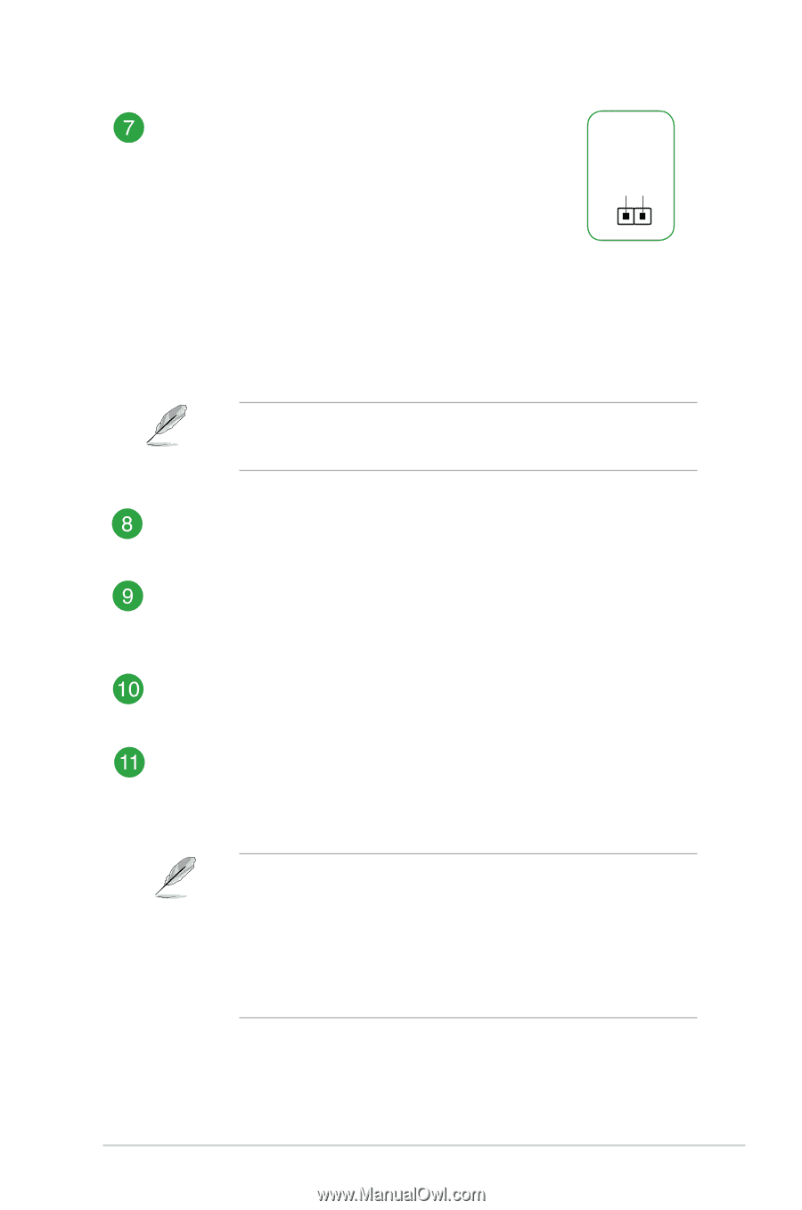
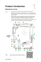
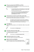
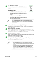
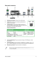
Clear RTC RAM (2-pin CLRTC) This header allows you to clear the CMOS RTC RAM data of the system setup information such as date, time, and system passwords. To erase the RTC RAM: 1. Turn OFF the computer and unplug the power cord. 2. Use a metal object such as a screwdriver to short the two pins. 3. Plug the power cord and turn ON the computer. 4. Hold down the key during the boot process and enter BIOS setup to re-enter data. +3V_BAT GND CLRTC PIN 1 If the steps above do not help, remove the onboard battery and short the two pins again to clear the CMOS RTC RAM data. After clearing the CMOS, reinstall the battery. Intel® Serial ATA 6.0Gb/s connectors (7-pin SATA6G_1~2) These connectors connect to Serial ATA 6.0 Gb/s hard disk drives via Serial ATA 6.0 Gb/s signal cables. USB 2.0 connector (10-1 pin USB34) Connect the USB module cable to this connector, then install the module to a slot opening at the back of the system chassis. This USB connector complies with USB 2.0 specifications and supports up to 480Mbps connection speed. Serial port connector (10-1 pin COM) Connect the serial port module cable to this connector, then install the module to a slot opening at the back of the system chassis. Front panel audio connector (10-1 pin AAFP) This connector is for a chassis-mounted front panel audio I/O module that supports either HD Audio or legacy AC`97 audio standard. Connect one end of the front panel audio I/O module cable to this connector. • We recommend that you connect a high-definition front panel audio module to this connector to avail of the motherboard's high-definition audio capability. • If you want to connect a high-definition front panel audio module to this connector, set the Front Panel Type item in the BIOS setup to [HD Audio]. If you want to connect an AC'97 front panel audio module to this connector, set the item to [AC97]. By default, this connector is set to [HD Audio]. ASUS J3455M-E 1-3
-
 1
1 -
2
-
3
-
4
-
 5
5 -
 6
6 -
 7
7 -
 8
8 -
 9
9 -
 10
10 -
 11
11 -
 12
12 -
 13
13 -
 14
14 -
 15
15 -
16
-
17
-
18
-
19
-
20
-
21
-
22
-
23
-
24
-
25
 |
 |