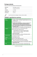
Asus J3455M-E J3455M-E Users ManualEnglish - Page 9
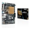
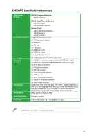
Quad Core Processor J3455, DDR3 DIMM slots
 |
View all Asus J3455M-E manuals
Add to My Manuals
Save this manual to your list of manuals |
Page 9 highlights
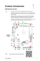
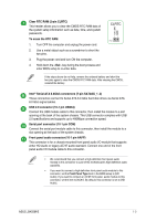
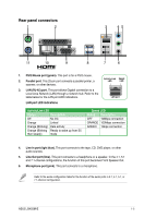
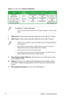
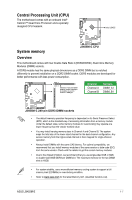
ATX power connectors (24-pin EATXPWR, 4-pin ATX12V) Correctly orient the ATX power supply plugs into these connectors and push down firmly until the connectors completely fit. • For a fully configured system, we recommend that you use a power supply unit (PSU) that complies with ATX 12 V Specification 2.0 (or later version) and provides a minimum power of 350 W. • If you are uncertain about the minimum power supply requirement for your system, refer to the Recommended Power Supply Wattage Calculator at http://support.asus.com/PowerSupplyCalculator/PSCalculator. aspx?SLanguage=en-us for details. CPU and chassis fan connectors (4-pin CPU_FAN, 4-pin CHA_FAN) Connect the fan cables to the fan connectors on the motherboard, ensuring that the black wire of each cable matches the ground pin of the connector. Do not forget to connect the fan cables to the fan connectors. Insufficient air flow inside the system may damage the motherboard components. These are not jumpers! Do not place jumper caps on the fan connectors! The CPU_FAN connector supports a CPU fan of maximum 1A (12 W) fan power. DDR3 DIMM slots Install 4 GB and 8 GB unbuffered non-ECC DDR3/DDR3L DIMMs into these DIMM sockets. For more details, refer to System memory. Intel® Celeron® Quad Core Processor J3455 The motherboard comes with an onboard Intel® Celeron™ Quad Core Processor and a specially designed CPU heatsink. For more details, refer to Central Processing Unit (CPU). System panel connector (10-1 pin F_PANEL) This connector supports several chassis-mounted functions. Speaker connector (4-pin SPEAKER) The 4-pin connector is for the chassis-mounted system warning speaker. The speaker allows you hear system beeps and warnings. SPEAKER +5V GND GND Speaker Out PIN 1 1-2 Chapter 1: Product introduction
-
 1
1 -
2
-
3
-
 4
4 -
 5
5 -
 6
6 -
 7
7 -
 8
8 -
 9
9 -
 10
10 -
 11
11 -
 12
12 -
 13
13 -
 14
14 -
15
-
16
-
17
-
18
-
19
-
20
-
21
-
22
-
23
-
24
-
25
 |
 |