Asus K8U-X K8U-X User's Manual for English Edition - Page 30
Internal connectors
 |
UPC - 737164057648
View all Asus K8U-X manuals
Add to My Manuals
Save this manual to your list of manuals |
Page 30 highlights
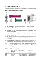
1.10.2 Internal connectors This section describes and illustrates the internal connectors on the motherboard. 1. IDE connectors (40-1 pin PRI_IDE, SEC_IDE) This connector supports the provided UltraATA133 IDE hard disk ribbon cable. Connect the cableʼs blue connector to the primary (recommended) or secondary IDE connector, then connect the gray connector to the UltraATA133 slave device (hard disk drive) and the black connector to the UltraATA133 master device. 1. Follow the hard disk drive documentation when setting the device in master or slave mode. 2. Pin 20 on each IDE connector is removed to match the covered hole on the UltraATA cable connector. This prevents incorrect orientation when you connect the cables. 3. The hole near the blue connector on the UltraATA cable is intentional. K8U-X PRI_IDE SEC_IDE NOTE: Orient the red markings (usually zigzag) on the IDE rNiboboten:caObrlieetnot PthINe1r.ed markings (usually zigzag) on the IDE ® ribbon cable to PIN 1. PIN 1 K8U-X IDE connectors PIN 1 1-20 Chapter 1: Product Introduction
-
 1
1 -
2
-
3
-
4
-
5
-
6
-
7
-
8
-
9
-
10
-
11
-
12
-
13
-
14
-
15
-
16
-
17
-
18
-
19
-
20
-
21
-
22
-
23
-
24
-
 25
25 -
 26
26 -
 27
27 -
 28
28 -
 29
29 -
 30
30 -
 31
31 -
 32
32 -
 33
33 -
 34
34 -
 35
35 -
36
-
37
-
38
-
39
-
40
-
41
-
42
-
43
-
44
-
45
-
46
-
47
-
48
-
49
-
50
-
51
-
52
-
53
-
54
-
55
-
56
-
57
-
58
-
59
-
60
-
61
-
62
-
63
-
64
-
65
-
66
-
67
-
68
-
69
-
70
-
71
-
72
-
73
-
74
-
75
-
76
-
77
-
78
-
79
-
80
 |
 |