Asus M2NPV-VM Motherboard Installation Guide - Page 46
IEEE 1394a connector 10-1 pinIE1394_1 [red], GAME/MIDI port connector 16-1 pin GAME
 |
View all Asus M2NPV-VM manuals
Add to My Manuals
Save this manual to your list of manuals |
Page 46 highlights
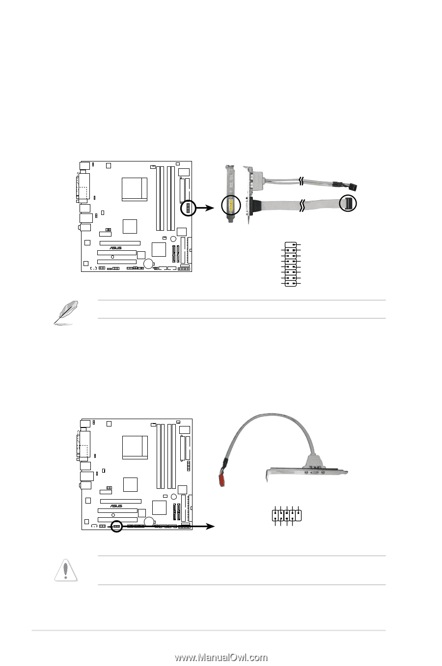
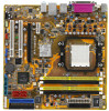
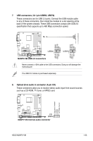
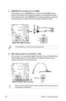
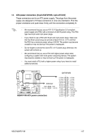
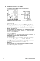
9. GAME/MIDI port connector (16-1 pin GAME) This connector is for a GAME/MIDI port. Connect the USB/GAME module cable to this connector, then install the module to a slot opening at the back of the system chassis. The GAME/MIDI port connects a joystick or game pad for playing games, and MIDI devices for playing or editing audio files. M2NPV-VM ® M2NPV-VM.GAME.connector GAME MIDI_IN J2B2 J2CY MIDI_OUT J2CX J2B1 +5V +5V J1B2 J1CY GND GND J1CX J1B1 +5V The GAME/MIDI port module is purchased separately. 10. IEEE 1394a connector (10-1 pinIE1394_1 [red]) This connector is for an additional IEEE 1394a port. Connect the IEEE 1394a module cable (orange) to this connector, then install the module to a slot opening at the back of the system chassis. TPA1GND TPB1+12V GND M2NPV-VM ® IE1394_1 1 M2NPV-VM.IEEE.1394a.connector TPA1+ GND TPB1+ +12V Never connect a USB port module cable to the IEEE 1394a connector. Doing so will damage the motherboard! 1-34 Chapter 1: Product introduction
-
 1
1 -
2
-
3
-
4
-
5
-
6
-
7
-
8
-
9
-
10
-
11
-
12
-
13
-
14
-
15
-
16
-
17
-
18
-
19
-
20
-
21
-
22
-
23
-
24
-
25
-
26
-
27
-
28
-
29
-
30
-
31
-
32
-
33
-
34
-
35
-
36
-
37
-
38
-
39
-
40
-
 41
41 -
 42
42 -
 43
43 -
 44
44 -
 45
45 -
 46
46 -
 47
47 -
 48
48 -
 49
49 -
 50
50 -
 51
51 -
52
-
53
-
54
-
55
-
56
-
57
-
58
-
59
-
60
-
61
-
62
-
63
-
64
-
65
-
66
-
67
-
68
-
69
-
70
-
71
-
72
-
73
-
74
-
75
-
76
-
77
-
78
-
79
-
80
-
81
-
82
-
83
-
84
-
85
-
86
-
87
-
88
-
89
-
90
-
91
-
92
-
93
-
94
-
95
-
96
-
97
-
98
-
99
-
100
-
101
-
102
 |
 |