Asus M4A78 User Manual
Asus M4A78 Manual
 |
View all Asus M4A78 manuals
Add to My Manuals
Save this manual to your list of manuals |
Asus M4A78 manual content summary:
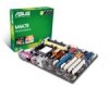
- Asus M4A78 | User Manual - Page 1
M4A78 Motherboard - Asus M4A78 | User Manual - Page 2
Product warranty or service will not be extended if: (1) the product is repaired, modified or altered, unless such repair, modification of alteration is authorized in writing by ASUS; or (2) the serial number of the product is defaced or missing. ASUS PROVIDES THIS MANUAL "AS IS" WITHOUT WARRANTY - Asus M4A78 | User Manual - Page 3
About this guide vii M4A78 specifications summary ix Chapter 1 Product introduction 1.1 Welcome 1-1 1.2 Package contents 1-1 1.3 Special features 1-1 1.3.1 Product highlights 1-1 1.3.2 Innovative ASUS features 1-3 1.4 Before you proceed 1-5 Onboard LED 1-5 1.5 Motherboard overview - Asus M4A78 | User Manual - Page 4
system 1-30 1.11.2 Support DVD information 1-30 Chapter 2 BIOS setup 2.1 Managing and updating your BIOS 2-1 2.1.1 ASUS Update utility 2-1 2.1.2 ASUS EZ Flash 2 utility 2-2 2.1.3 ASUS CrashFree BIOS 3 utility 2-3 2.2 BIOS setup program 2-4 2.2.1 BIOS menu screen 2-5 2.2.2 Menu - Asus M4A78 | User Manual - Page 5
Contents 2.4.4 Onboard Devices Configuration 2-14 2.4.5 PCI PnP 2-14 2.4.6 USB Configuration 2-15 2.5 Power menu 2-16 2.5.1 Suspend Mode 2-16 2.5.2 ACPI Support 2-16 2.5.3 ACPI APIC Support 2-16 2.5.4 APM Configuration 2-16 2.5.5 HW Monitor Configuration 2-17 2.6 Boot menu 2-18 2.6.1 Boot - Asus M4A78 | User Manual - Page 6
and, if not installed and used in accordance with manufacturer's instructions, may cause harmful interference to radio communications. However, there digital apparatus complies with Canadian ICES-003. DO NOT throw the motherboard in municipal waste. This product has been designed to enable proper - Asus M4A78 | User Manual - Page 7
. • If you encounter technical problems with the product, contact a qualified service technician or your retailer. About this guide This user guide contains the information you need when installing and configuring the motherboard. How this guide is organized This guide contains the following parts - Asus M4A78 | User Manual - Page 8
. IMPORTANT: Instructions that you MUST follow to complete a task. NOTE: Tips and additional information to help you complete a task. Where to find more information Refer to the following sources for additional information and for product and software updates. 1. ASUS websites The ASUS website - Asus M4A78 | User Manual - Page 9
unbuffered ECC DDR2 1066*/800/667/533MHz memory modules * DDR2 1066 is supported by AM2+ / AM3 CPU only. ** Refer to www.asus.com for the latest Memory QVL (Qualified Vendors List). *** When you install a total memory of 4GB capacity or more, Windows® 32-bit operating system may only recognize - Asus M4A78 | User Manual - Page 10
CPU/Chassis/Power Fan connectors 24-pin ATX power connector 4-pin ATX 12V power connector 8Mb Flash ROM, AMI BIOS, PnP, DMI v2.0, WfM2.0, ACPI2.0a, SM BIOS v2.5 1 x Serial ATA cable 1 x UltraDMA 133/100 cable 1x I/O Shield User manual ATX form factor: 12'' x 8.2'' (30.6cm x 20.9cm) Drivers ASUS - Asus M4A78 | User Manual - Page 11
motherboard package for the following items. Motherboard Cables Accessories Application DVD Documentations ASUS M4A78 motherboard 1 x Serial ATA cable 1 x Ultra DMA 133/100 cable 1 x I/O shield ASUS motherboard support DVD User manual -channel DDR2 1066 memory support and accelerates data transfer - Asus M4A78 | User Manual - Page 12
CPU only. Refer to www.asus.com for the AM3 / AM2+ CPU model. • Due to AM2+ CPU limitation, only one DDR2 1066 DIMM is supported per channel. When four DDR2 1066 DIMMs are installed, all DIMMs run at 800MHz frequency by default for system stability. PCI Express 2.0 support This motherboard supports - Asus M4A78 | User Manual - Page 13
motherboard supports next-generation SATA hard drives based on the new SATA 3Gb/s storage specification. The onboard SB700 southbridge allows RAID 0, RAID 1, RAID 0+1, and JBOD (only for Windows connectivity and ultra-fast data Innovative ASUS features ASUS EPU The ASUS EPU (Energy Processing Unit) - Asus M4A78 | User Manual - Page 14
you to restore a corrupted BIOS file using the bundled support DVD, or USB disk that contains the BIOS file. ASUS EZ Flash 2 ASUS EZ Flash 2 is a utility that allows you to update the BIOS without using an OS-based utility. ASUS Q-Fan ASUS Q-Fan technology intelligently adjusts CPU and chassis fan - Asus M4A78 | User Manual - Page 15
CPU Parameter Recall) The BIOS C.P.R. feature automatically restores the CPU default settings when the system hangs due to overclocking Failure to do so may cause severe damage to the motherboard, peripherals, or components. Onboard LED The motherboard comes with a standby power LED that lights up to - Asus M4A78 | User Manual - Page 16
part of the chassis as indicated in the image below. 1.5.2 Screw holes Place six screws into the holes indicated by circles to secure the motherboard to the chassis. Do not overtighten the screws! Doing so can damage the motherboard. Place this side towards the rear of the chassis. 1-6 ASUS M4A78 - Asus M4A78 | User Manual - Page 17
-1 pin PRI_EIDE) USBPW7-12) 2. ATX power connectors (24-pin EATXPWR, 4-pin ATX12V) 1-23 10. Onboard LED 3. Keyboard/mouse power (3-pin KBPWR) 1-20 11. System panel connector (20-8 pin F_PANEL) 4. CPU/Chassis/Power fan connectors (4-pin 1-29 12. USB connectors (10-1 pin USB78, USB910, CPU_FAN - Asus M4A78 | User Manual - Page 18
the CPU To install a CPU: 1. Locate the CPU socket on the motherboard. 2. Press the lever sideways to unlock the socket, then lift it up to a 90°100° angle. Socket lever Ensure that the socket lever is lifted up to 90°-100° angle, otherwise the CPU will not fit in completely. 1-8 ASUS M4A78 - Asus M4A78 | User Manual - Page 19
heatsink package. You can also refer to section 1.6.2 Installing heatsink and fan for instructions. Gold triangle 7. Connect the CPU fan cable to the CPU_FAN connector on the motherboard. Do not forget to connect the CPU fan connector! Hardware monitoring errors can occur if you fail to plug this - Asus M4A78 | User Manual - Page 20
assembly should come with installation instructions for the CPU, heatsink, and the retention mechanism. If the instructions in this section do not match the CPU documentation, follow the latter. 2. Attach one end of the retention bracket to the retention module base. 1 2 3 4 5 1-10 ASUS M4A78 - Asus M4A78 | User Manual - Page 21
labeled CPU_FAN. Do not forget to connect the CPU fan connector! Hardware monitoring errors can occur if you fail to plug this connector. 1.7 System memory 1.7.1 Overview The motherboard comes with four Double Data Rate 2 (DDR2) Dual Inline Memory Modules (DIMM) sockets. A DDR2 module has the same - Asus M4A78 | User Manual - Page 22
motherboard supports up to 16GB memory modules on Windows® XP Professional x64 and Vista x64 editions. You may install a maximum of 4GB DIMMs on each slot. M4A78 Motherboard -37B61921300CP Elixir DIMM support A* B* C* · · · · · · · · · · · · · · · · · · · · · 1-12 ASUS M4A78 - Asus M4A78 | User Manual - Page 23
0815 5-15 C7173S G.SKILL 5-5- Heat-Sink Package 5-15 G.SKILL 5 A3R12E3GEF633ACAOY PSC N/A K4T2G084QA-HCE6 Samsung 5 M2TU51280AE- 3C717095R28F ELIXIR 5 N2TU51280BE- 3C639009W1CF ELIXIR N/A HY5PS12821CFP-Y5 C 702AA Hynix DIMM support - Asus M4A78 | User Manual - Page 24
Transcend Elpida Transcend Elpida ADATA VDATA DIMM support · · · · · · · · · · · · · · · · · · · · · · · · · · · · · · · · · · · · · · · · · · · · · · · · · · · · · · · · · · · · · · · · · · · · · · · · · · 1-14 ASUS M4A78 - Asus M4A78 | User Manual - Page 25
-Sink Package OCZ 4 Heat-Sink Package OCZ 6 Heat-Sink Package OCZ 5 Heat-Sink Package OCZ 5 N2TU51280BE-25C802006Z1DV Elixir 5 N2TU16800E-AC Elixir 5 N2TUG80DE-AC Elixir DIMM support - Asus M4A78 | User Manual - Page 26
into both the yellow slots as one pair of Dual-channel memory configuration. • C*: Supports four modules inserted into both the yellow slots and the black slots as two pairs of Dual-channel memory configuration. Visit the ASUS website at www.asus.com for the latest QVL. 1-16 ASUS M4A78 - Asus M4A78 | User Manual - Page 27
system components. Failure to do so can cause severe damage to both the motherboard and the components. 1. Press the retaining clips outward to unlock a Simultaneously press the retaining clips outward to unlock the DIMM. Support the DIMM lightly with your fingers when pressing the retaining clips - Asus M4A78 | User Manual - Page 28
x1 slot This motherboard supports PCI Express x1 network cards, SCSI cards, and other cards that comply with the PCI Express specifications. 1.8.5 PCI Express x16 slot This motherboard supports a PCI Express x16 graphics card that complies with the PCI Express specifications. 1-18 ASUS M4A78 - Asus M4A78 | User Manual - Page 29
You can clear the CMOS memory of date, time, and system setup parameters by erasing the CMOS RTC RAM data. The onboard button cell battery powers the overclocking. For system failure due to overclocking, use the CPU Parameter Recall (C.P.R) feature. Shut down and reboot the system so the BIOS - Asus M4A78 | User Manual - Page 30
on the +5VSB lead, and a corresponding setting in the BIOS. This jumper is for the rear USB ports. 3. USB 5V to wake up the computer from S1 sleep mode (CPU stopped, DRAM refreshed, system running in low power mode) S3 and S4 sleep modes (no power to CPU, DRAM in slow refresh, power supply in reduced - Asus M4A78 | User Manual - Page 31
1.10 1.10.1 1 Connectors Rear panel connectors 2 3 4 56 7 8 15 14 13 12 11 10 9 1. PS/2 Keyboard/Mouse Combo port (purple). This port is for a PS/2 keyboard or mouse. 2. Parallel port. This 25-pin port connects a parallel printer, a scanner, or other devices. 3. USB 2.0 ports 3 and 4. - Asus M4A78 | User Manual - Page 32
pointing devices or other serial devices. 15. USB 2.0 ports 5 and 6. These two 4-pin Universal Serial Bus (USB) ports are available for connecting USB 2.0 devices. 1-22 ASUS M4A78 - Asus M4A78 | User Manual - Page 33
is inadequate. • If you are uncertain about the minimum power supply requirement for your system, refer to the Recommended Power Supply Wattage Calculator at http://support.asus. com/PowerSupplyCalculator/PSCalculator.aspx?SLanguage=en-us for details. Chapter 1: Product introduction 1-23 - Asus M4A78 | User Manual - Page 34
) The onboard IDE connector is for Ultra DMA 133/100 signal cable. There are three connectors on each Ultra DMA 133 / 100 signal cable: blue, black, and gray. Connect the blue connector to the motherboard's IDE connector ensure that all other device jumpers have the same setting. 1-24 ASUS M4A78 - Asus M4A78 | User Manual - Page 35
onboard SB700 chipset. Install the Windows® XP Service Pack 1 before using Serial ATA. • For detailed instructions on RAID configurations, refer to the RAID manual in the support DVD. • If you intend to create a Serial ATA RAID set using these connectors, set the Onchip SATA Type item in the BIOS - Asus M4A78 | User Manual - Page 36
connector supports BIOS settings. Pressing the power switch for more than four seconds while the system is ON turns the system OFF. • Reset button (2-pin RESET) This 2-pin connector is for the chassis-mounted reset button for system reboot without turning off the system power. 1-26 ASUS M4A78 - Asus M4A78 | User Manual - Page 37
back of the system chassis. These USB connectors comply with USB 2.0 specification that supports up to 480 Mbps connection speed. Never connect a 1394 cable to the USB connectors. Doing so will damage the motherboard! The USB 2.0 module is purchased separately. Chapter 1: Product introduction 1-27 - Asus M4A78 | User Manual - Page 38
on the OS). Go to Start > Control Panel > Sounds and Audio Devices > Sound Playback to configure the setting. The S/PDIF module is purchased separately. 1-28 ASUS M4A78 - Asus M4A78 | User Manual - Page 39
not forget to connect the fan cables to the fan connectors. Insufficient air flow inside the system may damage the motherboard components. These are not jumpers! Do not place jumper caps on the fan connectors! Only the CPU fan supports the ASUS Q-FAN feature. Chapter 1: Product introduction 1-29 - Asus M4A78 | User Manual - Page 40
you install Windows® XP Service Pack 3 or later versions/ Windows® Vista Service Pack 1 or later versions before installing the drivers for better compatibility and system stability. 1.11.2 Support DVD information The Support DVD that comes with the motherboard package contains the drivers, software - Asus M4A78 | User Manual - Page 41
motherboard package. Installing ASUS Update To install ASUS Update: 1. Place the support DVD in the optical drive. The Drivers menu appears. 2. Click the Utilities tab, then click Install ASUS Update. 3. Follow the onscreen instructions to complete the installation. Quit all Windows® applications - Asus M4A78 | User Manual - Page 42
the BIOS update process and automatically reboots the system when done. • This function can support devices such as USB flash disk with FAT 32/16 format and single partition only. • Do not shut down or reset the system while updating the BIOS to prevent system boot failure! 2-2 ASUS M4A78 - Asus M4A78 | User Manual - Page 43
ASUS CrashFree BIOS 3 utility The ASUS CrashFree BIOS 3 is an auto recovery tool that allows you to restore the BIOS file when it fails or gets corrupted during the updating process. You can update a corrupted BIOS file using the motherboard support DVD or a USB flash disk that contains the updated - Asus M4A78 | User Manual - Page 44
item under the Exit Menu. See section 2.8 Exit Menu. • The BIOS setup screens shown in this section are for reference purposes only, and may not exactly match what you see on your screen. • Visit the ASUS website at www.asus.com to download the latest BIOS file for this motherboard. 2-4 ASUS M4A78 - Asus M4A78 | User Manual - Page 45
Menu bar Configuration fields General help Main Advanced Power BIOS SETUP UTILITY Boot Tools Exit System Time 19:34 left arrow key on the keyboard until the desired item is highlighted. • The BIOS setup screens shown in this chapter are for reference purposes only, and may not exactly match - Asus M4A78 | User Manual - Page 46
pop-up window with the configuration options for that item. Main Advanced BIOS SETUP UTILITY Power Boot Tools Exit Suspend Mode ACPI Support ACPI APIC support APM Configuration Hardware .61 (C)Copyright 1985-2008, A m e r i c a n Megatrends, Inc. Pop-up window Scroll bar 2-6 ASUS M4A78 - Asus M4A78 | User Manual - Page 47
the system date. 2.3.3 Primary IDE Master/Slave While entering Setup, the BIOS automatically detects the presence of IDE devices. There is a separate submenu for . Setting to [Auto] enables the LBA mode if the device supports this mode, and if the device was not previously formatted with LBA mode - Asus M4A78 | User Manual - Page 48
the device occurs multiple sectors at a time if the device supports multi-sector transfer feature. When set to [Disabled], the then press to display the SATA device information. The BIOS automatically detects the values opposite the dimmed items (Device, Vendor, ] [Enabled] 2-8 ASUS M4A78 - Asus M4A78 | User Manual - Page 49
RAID] [AHCI] When SATA is configured as [AHCI] in BIOS, only SATA port 1-3 can be detected. Ensure to install the AHCI driver to detect and use SATA port 1, 2, 3, 5, 6 in Power BIOS SETUP UTILITY Boot Tools Exit JumperFree Configuration CPU Configuration Chipset Onboard Devices Configuration - Asus M4A78 | User Manual - Page 50
system. • Overclock Profile - Loads overclocking profiles with optimal parameters for stability when overclocking. The following item appears only when the CPU Overclocking item is set to [Manual]. CPU/HT Reference run at this width. Configuration options: [Auto] [8 Bit] [16 Bit] 2-10 ASUS M4A78 - Asus M4A78 | User Manual - Page 51
[Auto] Allows you to set the memory clock mode. Configuration options: [Auto] [Manual] The following item appears only when the Memory clock mode item is set to [Manual]. Memclock Value [200 MHz] Allows the same DRAM. Configuration options: [1 CLK] [2 CLK] [3 CLK] [Auto] Chapter 2: BIOS setup 2-11 - Asus M4A78 | User Manual - Page 52
show the CPU-related information that the BIOS automatically detects. GART Error Reporting [Disabled] This option should remain disabled for the normal operation. The driver developer may enable it for testing purpose. Configuration options: [Disabled] [Enabled] Microcode Updation [Enabled] Allows - Asus M4A78 | User Manual - Page 53
disables the DRAM ECC that allows the hardware to report and correct memory errors automatically. Configuration options: [Disabled] [Basic] [Good] [ GFX-GPP-PCI] Allows you to set the primary display adapter. Configuration options: [GFX-GPP-PCI] [GPPGFX-PCI] [PCI-GFX-GPP] Chapter 2: BIOS setup 2- - Asus M4A78 | User Manual - Page 54
. Plug and Play O/S [No] When set to [No], BIOS configures all the devices in the system. When set to [Yes] and if you install a Plug and Play operating system, the operating system configures the Plug and Play devices not required for boot. Configuration options: [No] [Yes] 2-14 ASUS M4A78 - Asus M4A78 | User Manual - Page 55
mode is enabled. If no USB device is detected, the legacy USB support is disabled. Configuration options: [Disabled] [Enabled] [Auto] USB Storage Reset Delay [20 Sec] Allows you to set the maximum time that the BIOS waits for the USB storage device to initialize. Configuration options: [10 Sec] [20 - Asus M4A78 | User Manual - Page 56
its working state exactly where it was left off. [Auto] - Detected by OS. 2.5.2 ACPI Support [Disabled] Allows you to add more tables for Advanced Configuration and Power Interface (ACPI) 2.0 specifications. AC power loss. Configuration options: [Power On] [Power Off] [Last State] 2-16 ASUS M4A78 - Asus M4A78 | User Manual - Page 57
with set values. Configuration options: [Disabled] [Enabled] 2.5.5 HW Monitor Configuration CPU Temperature [xxxºC/xxxºF] MB Temperature [xxxºC/xxxºF] The onboard hardware monitor automatically detects and displays the motherboard and CPU temperatures. Select Ignored if you do not wish to display - Asus M4A78 | User Manual - Page 58
or disable the full screen logo display feature. Configuration options: [Disabled] [Enabled] Set this item to [Enabled] to use the ASUS MyLogo 2™ feature. AddOn ROM Display Mode [Force BIOS] Sets the display mode for option ROM. Configuration options: [Force BIOS] [Keep Current] 2-18 ASUS M4A78 - Asus M4A78 | User Manual - Page 59
. To clear the supervisor password, select the Change Supervisor Password then press twice. The message "Password Uninstalled" appears. If you forget your BIOS password, you can clear it by erasing the CMOS Real Time Clock (RTC) RAM. See section "1.9 Jumpers" for information on how to erase - Asus M4A78 | User Manual - Page 60
2.7 Tools menu Main Advanced Power BIOS SETUP UTILITY Boot Tools Exit ASUS EZ Flash 2 Express Gate [Auto] Enter OS Timer [10 Seconds] Reset User Date [No] AI NET2 Press ENTER to run the utility to select and update BIOS. This utility doesn't support : 1.NTFS format Select Screen Select - Asus M4A78 | User Manual - Page 61
ASUS Express Gate feature is a unique instant-on environment that provides quick access to the Internet browser and Skype. Configuration options: [Enabled] [Disabled] Enter OS Timer [10 Seconds] Sets countdown duration that the system waits at the Express Gate's first screen before starting Windows - Asus M4A78 | User Manual - Page 62
the CMOS RAM. An onboard backup battery sustains the CMOS RAM System Time, and Password, the BIOS asks for a confirmation before window appears. Select OK to load default values. Select Exit & Save Changes or make other changes before saving the values to the non-volatile RAM. 2-22 ASUS M4A78
-
 1
1 -
 2
2 -
 3
3 -
 4
4 -
 5
5 -
 6
6 -
 7
7 -
8
-
9
-
10
-
11
-
12
-
13
-
14
-
15
-
16
-
17
-
18
-
19
-
20
-
21
-
22
-
23
-
24
-
25
-
26
-
27
-
28
-
29
-
30
-
31
-
32
-
33
-
34
-
35
-
36
-
37
-
38
-
39
-
40
-
41
-
42
-
43
-
44
-
45
-
46
-
47
-
48
-
49
-
50
-
51
-
52
-
53
-
54
-
55
-
56
-
57
-
58
-
59
-
60
-
61
-
62
 |
 |

Motherboard
M4A78