Asus M4A78 User Manual - Page 39
Front panel audio connector 10-1 pin AAFP, CPU, Chassis, and PowerFan connectors 4 pin CPU_FAN, 3-
 |
View all Asus M4A78 manuals
Add to My Manuals
Save this manual to your list of manuals |
Page 39 highlights
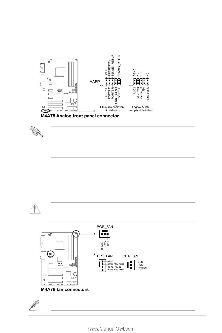
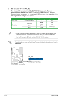
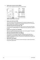
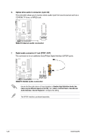
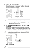
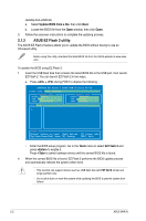
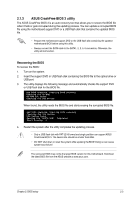
8. Front panel audio connector (10-1 pin AAFP) This connector is for a chassis-mounted front panel audio I/O module that supports either High Definition Audio or AC`97 audio standard. Connect one end of the front panel audio I/O module cable to this connector. • We recommend that you connect a high-definition front panel audio module to this connector to avail of the motherboard high-definition audio capability. • By default, this connector is set to [HD Audio]. If you want to connect an AC97 front panel audio module to this connector, set the item in the BIOS to [AC 97]. See section "2.4.4 Onboard Device Configuration" for details. 9. CPU, Chassis, and PowerFan connectors (4 pin CPU_FAN, 3-pin CHA_FAN, and 3-pin PWR_FAN) The fan connectors support cooling fans of 350mA~740mA (8.88W max.) or a total of 1A~2.22A (26.64W max.) at +12V. Connect the fan cables to the fan connectors on the motherboard, ensuring that the black wire of each cable matches the ground pin of the connector. Do not forget to connect the fan cables to the fan connectors. Insufficient air flow inside the system may damage the motherboard components. These are not jumpers! Do not place jumper caps on the fan connectors! Only the CPU fan supports the ASUS Q-FAN feature. Chapter 1: Product introduction 1-29
-
 1
1 -
2
-
3
-
4
-
5
-
6
-
7
-
8
-
9
-
10
-
11
-
12
-
13
-
14
-
15
-
16
-
17
-
18
-
19
-
20
-
21
-
22
-
23
-
24
-
25
-
26
-
27
-
28
-
29
-
30
-
31
-
32
-
33
-
 34
34 -
 35
35 -
 36
36 -
 37
37 -
 38
38 -
 39
39 -
 40
40 -
 41
41 -
 42
42 -
 43
43 -
 44
44 -
45
-
46
-
47
-
48
-
49
-
50
-
51
-
52
-
53
-
54
-
55
-
56
-
57
-
58
-
59
-
60
-
61
-
62
 |
 |