Asus M4A78LT PLUS User Manual - Page 27
Internal connectors
 |
View all Asus M4A78LT PLUS manuals
Add to My Manuals
Save this manual to your list of manuals |
Page 27 highlights
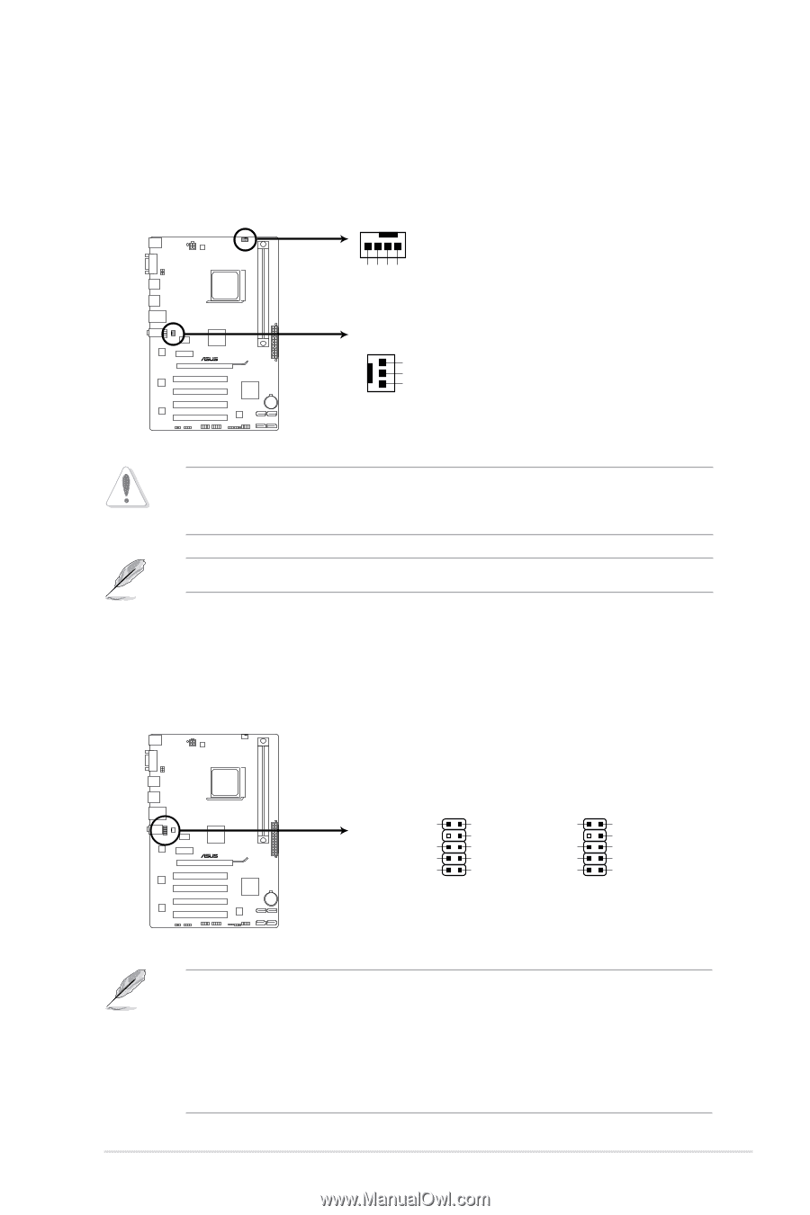
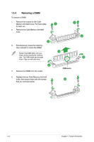
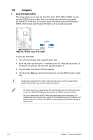
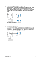
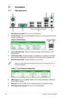
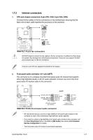
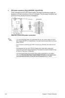
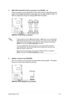
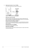
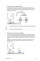
1.7.2 Internal connectors 1. CPU and chassis connectors (4-pin CPU_FAN; 3-pin CHA_FAN) Connect the fan cables to the fan connectors on the motherboard, ensuring that the black wire of each cable matches the ground pin of the connector. CPU_FAN CPU FAN PWM CPU FAN IN CPU FAN PWR GND M4A78LT PLUS CHA_FAN GND +12V Rotation M4A78LT PLUS fan connectors DO NOT forget to connect the fan cables to the fan connectors. Insufficient air flow inside the system may damage the motherboard components. These are not jumpers! DO NOT place jumper caps on the fan connectors. Only the 4-pin CPU fan supports the ASUS Q-Fan feature. 2. Front panel audio connector (10-1 pin AAFP) This connector is for a chassis-mounted front panel audio I/O module that supports either High Definition Audio or AC`97 audio standard. Connect one end of the front panel audio I/O module cable to this connector. M4A78LT PLUS AAFP SENSE2_RETUR SENSE1_RETUR PRESENCE# GND PORT2 L NC SENSE_SEND PORT2 R NC PORT1 R NC PORT1 L PIN 1 AGND Line out_L NC Line out_R MICPWR MIC2 PIN 1 HD-audio-compliant pin definition Legacy AC'97 compliant definition M4A78LT PLUS Front panel audio connector • We recommend that you connect a high-definition front panel audio module to this connector to avail of the motherboard high-definition audio capability. • If you want to connect a high definition front panel audio module to this connector, set the Front Panel Select item in the BIOS to [HD Audio]. See section 2.4.3 Onboard Devices Configuration for details. • The front panel audio I/O module is purchased separately. ASUS M4A78LT PLUS 1-17
-
 1
1 -
2
-
3
-
4
-
5
-
6
-
7
-
8
-
9
-
10
-
11
-
12
-
13
-
14
-
15
-
16
-
17
-
18
-
19
-
20
-
21
-
 22
22 -
 23
23 -
 24
24 -
 25
25 -
 26
26 -
 27
27 -
 28
28 -
 29
29 -
 30
30 -
 31
31 -
 32
32 -
33
-
34
-
35
-
36
-
37
-
38
-
39
-
40
-
41
-
42
-
43
-
44
-
45
-
46
-
47
-
48
-
49
-
50
-
51
-
52
-
53
-
54
-
55
-
56
 |
 |