Asus M5A78L LE User Manual - Page 18
Central Processing Unit CPU - am3
 |
View all Asus M5A78L LE manuals
Add to My Manuals
Save this manual to your list of manuals |
Page 18 highlights
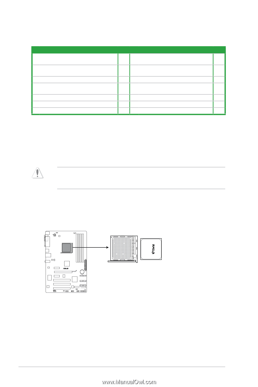
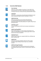
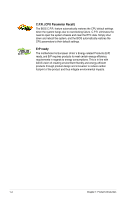
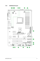
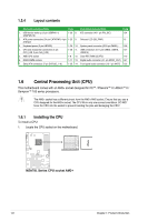
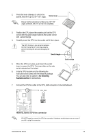
1.5.4 Layout contents Connectors/Jumpers/Slots Page Connectors/Jumpers/Slots Page 1. USB device wake-up (3-pin USBPW1-4, 1-20 8. IDE connector (40-1 pin PRI_IDE) 1-24 USBPW5-10) 2. ATX power connectors (24-pin EATXPWR, 4-pin 1-23 9. Onboard LED (SB_PWR) 1-5 ATX12V) 3. Keyboard power (3-pin KBPWR) 1-20 10. System panel connector (20-8 pin PANEL) 1-26 4. CPU and chassis fan connectors (4-pin CPU_FAN, 3-pin CHA_FAN) 1-28 11. USB connectors (10-1 pin USB56, USB78, 1-27 USB910) 5. AMD CPU socket 1-8 12. Clear RTC RAM (CLRTC) 1-19 6. DDR3 DIMM sockets 1-11 13. Digital audio connector (4-1 pin SPDIF_OUT) 1-27 7. Serial ATA connectors (7-pin SATA3G_1~6) 1-25 14. Front panel audio connector (10-1 pin AAFP) 1-22 1.6 Central Processing Unit (CPU) This motherboard comes with an AM3+ socket designed for FX™ / Phenom™ II / Athlon™ II / Sempron™ 100 series processors. The AM3+ socket has a different pinout from the AM2+/AM2 socket. Ensure that you use a CPU designed for the AM3+ socket. The CPU fits in only one correct orientation. DO NOT force the CPU into the socket to prevent bending the pins and damaging the CPU! 1.6.1 Installing the CPU To install a CPU: 1. Locate the CPU socket on the motherboard. M5A78L Series M5A78L Series CPU socket AM3+ 1-8 Chapter 1: Product introduction
-
 1
1 -
2
-
3
-
4
-
5
-
6
-
7
-
8
-
9
-
10
-
11
-
12
-
 13
13 -
 14
14 -
 15
15 -
 16
16 -
 17
17 -
 18
18 -
 19
19 -
 20
20 -
 21
21 -
 22
22 -
 23
23 -
24
-
25
-
26
-
27
-
28
-
29
-
30
-
31
-
32
-
33
-
34
-
35
-
36
-
37
-
38
-
39
-
40
-
41
-
42
-
43
-
44
-
45
-
46
-
47
-
48
-
49
-
50
-
51
-
52
-
53
-
54
-
55
-
56
-
57
-
58
-
59
-
60
-
61
-
62
-
63
-
64
-
65
-
66
 |
 |