Asus M5A78L-M PLUS/USB3 M5A78L-M PLUS/USB3 Users manual English - Page 10
Clear RTC RAM 2-pin CLRTC, To erase the RTC RAM - am3
 |
View all Asus M5A78L-M PLUS/USB3 manuals
Add to My Manuals
Save this manual to your list of manuals |
Page 10 highlights
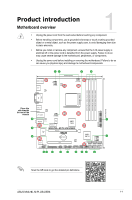
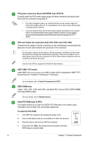
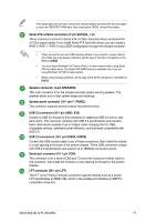
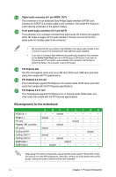
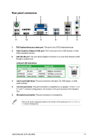
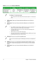
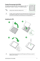
ATX power connectors (24-pin EATXPWR, 4-pin ATX12V) Correctly orient the ATX power supply plugs into these connectors and push down firmly until the connectors completely fit. • For a fully configured system, we recommend that you use a power supply unit (PSU) that complies with ATX 12 V Specification 2.0 (or later version) and provides a minimum power of 300 W. • If you are uncertain about the minimum power supply requirement for your system, refer to the Recommended Power Supply Wattage Calculator at http://support. asus.com/PowerSupplyCalculator/PSCalculator.aspx?SLanguage=en-us for details. CPU and chassis fan connectors (4-pin CPU_FAN, 4-pin CHA_FAN) Connect the fan cables to the fan connectors on the motherboard, ensuring that the black wire of each cable matches the ground pin of the connector. Do not forget to connect the fan cables to the fan connectors. Insufficient air flow inside the system may damage the motherboard components. These are not jumpers! Do not place jumper caps on the fan connectors! The CPU_FAN connector supports a CPU fan of maximum 2A (24 W) fan power. Only the 4-pin CPU fan supports the ASUS Fan Xpert feature. AMD® AM3+ CPU socket Install AMD® CPU into this surface mount AM3+ socket, which is designed for AMD® FX™ Series/Phenom™ II/Athlon™ II/Sempron™ 100 Series. For more details, refer to Central Processing Unit (CPU). DDR3 DIMM slots Install 1 GB, 2 GB, 4 GB, and 8 GB, unbuffered ECC and non-ECC DDR3 DIMMs into these DIMM sockets. For more details, refer to System memory. Clear RTC RAM (2-pin CLRTC) This header allows you to clear the CMOS RTC RAM data of the system setup information such as date, time, and system passwords. To erase the RTC RAM: 1. Turn OFF the computer and unplug the power cord. 2. Use a metal object such as a screwdriver to short the two pins. 3. Plug the power cord and turn ON the computer. 4. Hold down the key during the boot process and enter BIOS setup to re-enter data. +3V_BAT GND CLRTC PIN 1 1-2 Chapter 1: Product introduction
-
 1
1 -
2
-
3
-
4
-
 5
5 -
 6
6 -
 7
7 -
 8
8 -
 9
9 -
 10
10 -
 11
11 -
 12
12 -
 13
13 -
 14
14 -
 15
15 -
16
-
17
-
18
-
19
-
20
-
21
-
22
-
23
-
24
-
25
-
26
-
27
 |
 |