Asus MAXIMUS FORMULA SE Motherboard Installation Guide - Page 58
IEEE 1394a port connector 10-1 pin IE1394_2, Thermal sensor cable connectors 2-pin OPT_TEMP1/2/3 - maximus formula v bios
 |
View all Asus MAXIMUS FORMULA SE manuals
Add to My Manuals
Save this manual to your list of manuals |
Page 58 highlights
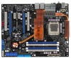
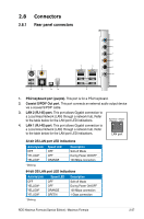
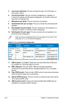
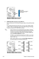
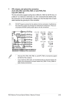
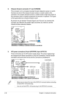
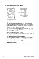
5. IEEE 1394a port connector (10-1 pin IE1394_2) This connector is for a IEEE 1394a port. Connect the IEEE 1394a module cable to this connector, then install the module to a slot opening at the back of the system chassis. ® GND +12V TPB1GND TPA1- MAXIMUS FORMULA IE1394_2 PIN 1 +12V TPB1+ GND TPA1+ MAXIMUS FORMULA(Special Edition)/ MAXIMUS FORMULA IEEE 1394a connector Never connect a USB cable to the IEEE 1394a connector. Doing so will damage the motherboard! You can connect the 1394 cable to ASUS Q-Connector (1394, red) first, and then install the Q-Connector (1394) to the 1394 connector onboard. 6. Thermal sensor cable connectors (2-pin OPT_TEMP1/2/3) These connectors are for temperature monitoring. Connect the thermal sensor cables to these connectors and place the other ends to the devices which you want to monitor temperature. The optional fan1/2/3 can work with the temperature sensors for a better cooling effect. Temperature Ground Temperature Ground ® OPT_TEMP1 MAXIMUS FORMULA OPT_TEMP2 MAXIMUS FORMULA(Special Edition)/ MAXIMUS FORMULA Thermal sensor cable connectors OPT_TEMP3 Temperature Ground Enable OPT_TEMP1/2/3 Overheat Protection in BIOS if you connect thermal sensor cables to these connectors. Refer to page 4-31 for details. The thermal sensor cable is purchased separately. 2-32 Chapter 2: Hardware information
-
 1
1 -
2
-
3
-
4
-
5
-
6
-
7
-
8
-
9
-
10
-
11
-
12
-
13
-
14
-
15
-
16
-
17
-
18
-
19
-
20
-
21
-
22
-
23
-
24
-
25
-
26
-
27
-
28
-
29
-
30
-
31
-
32
-
33
-
34
-
35
-
36
-
37
-
38
-
39
-
40
-
41
-
42
-
43
-
44
-
45
-
46
-
47
-
48
-
49
-
50
-
51
-
52
-
 53
53 -
 54
54 -
 55
55 -
 56
56 -
 57
57 -
 58
58 -
 59
59 -
 60
60 -
 61
61 -
 62
62 -
 63
63 -
64
-
65
-
66
-
67
-
68
-
69
-
70
-
71
-
72
-
73
-
74
-
75
-
76
-
77
-
78
-
79
-
80
-
81
-
82
-
83
-
84
-
85
-
86
-
87
-
88
-
89
-
90
-
91
-
92
-
93
-
94
-
95
-
96
-
97
-
98
-
99
-
100
-
101
-
102
-
103
-
104
-
105
-
106
-
107
-
108
-
109
-
110
-
111
-
112
-
113
-
114
-
115
-
116
-
117
-
118
-
119
-
120
-
121
-
122
-
123
-
124
-
125
-
126
-
127
-
128
-
129
-
130
-
131
-
132
-
133
-
134
-
135
-
136
-
137
-
138
-
139
-
140
-
141
-
142
-
143
-
144
-
145
-
146
-
147
-
148
-
149
-
150
-
151
-
152
-
153
-
154
-
155
-
156
-
157
-
158
-
159
-
160
-
161
-
162
-
163
-
164
-
165
-
166
-
167
-
168
 |
 |
