Asus NR-LSR NR-LSR User Manual - Page 39
Switches
 |
View all Asus NR-LSR manuals
Add to My Manuals
Save this manual to your list of manuals |
Page 39 highlights
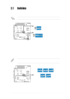
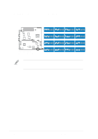
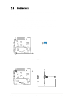
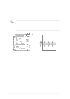
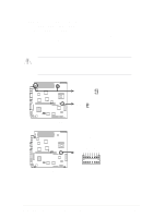
2.7 Switches The following figure shows the location and default settings of the DIP switches on the motherboard. Keep the default settings for stable system operation. OFF ON OFF ON ® NR-LSR NR-LSR DIP Switches ON 12345678 ON 12345 CLKSW U78 1.Frequency Selection 2.Frequency Selection 3.Frequency Selection 4.Frequency Selection 5.Spread Spectrum 1.Reserved 2.Reserved 3.Reserved 4.Reserved 5.Frequency Multiple 6.Frequency Multiple 7.Frequency Multiple 8.Frequency Multiple 1. CPU external frequency selection (CLKSW Switches 1-5) This option tells the clock generator what frequency to send the CPU. This allows the selection of the CPU's external frequency (or Bus Clock). The BUS Clock multiplied by the Frequency Multiple equals the CPU's internal frequency (the advertised CPU speed). To select the CPU external frequency using the DIP switches, ensure that the JEN jumper is set to jumper mode. CLKSW ON 12345 ON 12345 ON 12345 CPU 100MHz 101MHz 103MHz ON 12345 ON 12345 ® NR-LSR NR-LSR CPU External Frequency Selection CPU 105MHz 110MHz ASUS NR-LSR motherboard user guide 2-13
-
 1
1 -
2
-
3
-
4
-
5
-
6
-
7
-
8
-
9
-
10
-
11
-
12
-
13
-
14
-
15
-
16
-
17
-
18
-
19
-
20
-
21
-
22
-
23
-
24
-
25
-
26
-
27
-
28
-
29
-
30
-
31
-
32
-
33
-
 34
34 -
 35
35 -
 36
36 -
 37
37 -
 38
38 -
 39
39 -
 40
40 -
 41
41 -
 42
42 -
 43
43 -
 44
44 -
45
-
46
-
47
-
48
-
49
-
50
-
51
-
52
-
53
-
54
-
55
-
56
-
57
-
58
-
59
-
60
-
61
-
62
-
63
-
64
-
65
-
66
-
67
-
68
-
69
-
70
-
71
-
72
-
73
-
74
-
75
-
76
-
77
-
78
-
79
-
80
-
81
-
82
-
83
-
84
-
85
-
86
-
87
-
88
-
89
-
90
-
91
-
92
-
93
-
94
-
95
-
96
-
97
-
98
-
99
-
100
-
101
-
102
-
103
-
104
-
105
-
106
 |
 |
