Asus P I-XP55T2P4 User Manual - Page 14
Total Level 2 Cache Size Setting, IMPORTANT, See SRAM Cache for installation procedures.,
 |
View all Asus P I-XP55T2P4 manuals
Add to My Manuals
Save this manual to your list of manuals |
Page 14 highlights
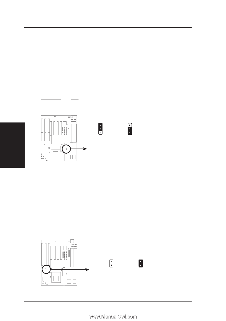
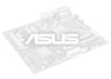
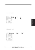
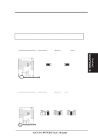
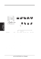
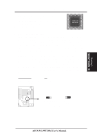
III. INSTALLATION (Jumpers) III. INSTALLATION 3. Total Level 2 Cache Size Setting (JP5) This jumper sets the total amount of L2 cache that is present. If you have both onboard cache chips (see "Map of Motherboard" for locations) and a Cache Expansion Slot, then you have 256KB. If you only have onboard cache chips, then you have 512KB. An "ASUS" or "COAST" cache module can be used to upgrade the 256KB version to 512KB. If there is no onboard cache, you may install a cache module of either 256KB or 512KB. IMPORTANT: See page 14 "SRAM Cache" for installation procedures. Regardless of your cache combination, set the following jumpers according to the total amount of L2 cache that is present onboard and installed as a module. Selections JP5 256KB [1-2] 512KB [2-3] JP5 1 2 3 256KB JP5 1 2 3 512KB Total L2 Cache Size Setting (256KB / 512KB) 4. Real Time Clock (RTC) RAM (JP7) This clears the user-entered information stored in the CMOS RAM of the Real Time Clock such as hard disk information and passwords. To clear the RTC data: (1) Turn off the PC, (2) Short this jumper, (3) Power on the PC, (4) Turn off the PC, (5) Remove this jumper, (6) Power on the PC, (7) Hold down during bootup and enter BIOS setup to re-enter user preferences. Selections JP7 Operation [open] (Default) Clear Data [short] (momentarily) JP7 JP7 Operation (Default) Clear Data RTC RAM (Operation / Clear Data) 8 ASUS P/I-P55T2P4 User's Manual
-
 1
1 -
2
-
3
-
4
-
5
-
6
-
7
-
8
-
 9
9 -
 10
10 -
 11
11 -
 12
12 -
 13
13 -
 14
14 -
 15
15 -
 16
16 -
 17
17 -
 18
18 -
 19
19 -
20
-
21
-
22
-
23
-
24
-
25
-
26
-
27
-
28
-
29
-
30
-
31
-
32
-
33
-
34
-
35
-
36
-
37
-
38
-
39
-
40
-
41
-
42
-
43
-
44
-
45
-
46
-
47
-
48
-
49
-
50
-
51
-
52
-
53
-
54
-
55
-
56
-
57
-
58
-
59
-
60
-
61
-
62
-
63
-
64
 |
 |