Asus P3-P5G43 User Manual - Page 14
Rear panel
 |
View all Asus P3-P5G43 manuals
Add to My Manuals
Save this manual to your list of manuals |
Page 14 highlights
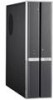
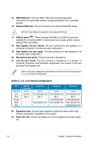
1.3 Rear panel The system rear panel includes the power connector and several I/O ports that allow convenient connection of devices. 1 2 34 5 67 8 9 10 11 1 HDMI DVI 1394 ESATA 12 13 14 15 16 17 18 19 20 21 22 23 1. Cover screw. Secures the system cover. 2. PS/2 keyboard port . This 6-pin connector is for a PS/2 keyboard. 3. Air vent. Provides ventilation for the system. 4. VGA port . Connects a VGA monitor. 5. USB 2.0 available pfoorrtcsonnecti.nTghUesSeBU2n.0ivdeeHrsvDaicMl eSIsesriuaclDhBVIuass 2.0 (USB a mouse, 2.0) p1o3rt9s4are printer, scanner, camera, PDA, and others. 6. LAN (RJ-45) port . This port allows Fast Ethernet connectioEnStAoTaA Local Area Network (LAN) through a network hub. 7. Center / Subwoofer port (orange). This port connects the center / subwoofer speakers. 8. Line In port (light blue). This port connects a tape, CD, DVD player, or other audio sources. 9. Metal bracket lock. Secures the expansion slot/card metal brackets. 10. Voltage selector. Allows you to adjust the system input voltage according to the voltage supply in your area. If the voltage supply in your area is 100-127 V, set the switch to 115 V. If the voltage supply in your area is 200-240 V, set the switch to 230 V. Setting the switch to 115 V in a 230 V environment will seriously damage the system! 11. Power connector. Connects the power cable and plug. 12. USB 2.0 ports . These Universal Serial Bus 2.0 (USB 2.0) ports are available for connecting USB 2.0 devices such as a mouse, printer, scanner, camera, PDA, and others. 1-4 Chapter 1: System introduction
-
 1
1 -
2
-
3
-
4
-
5
-
6
-
7
-
8
-
 9
9 -
 10
10 -
 11
11 -
 12
12 -
 13
13 -
 14
14 -
 15
15 -
 16
16 -
 17
17 -
 18
18 -
 19
19 -
20
-
21
-
22
-
23
-
24
-
25
-
26
-
27
-
28
-
29
-
30
-
31
-
32
-
33
-
34
-
35
-
36
-
37
-
38
-
39
-
40
-
41
-
42
-
43
-
44
-
45
-
46
-
47
-
48
-
49
-
50
-
51
-
52
-
53
-
54
-
55
-
56
-
57
-
58
-
59
-
60
-
61
-
62
-
63
-
64
-
65
-
66
-
67
-
68
-
69
-
70
-
71
-
72
-
73
-
74
-
75
-
76
-
77
-
78
 |
 |
