Asus P4BGV-MX P4BGV-MX User Manual - Page 24
Motherboard Information, ATX power connectors 20-pin ATX_POWER1, USB headers 10-1 pin
 |
View all Asus P4BGV-MX manuals
Add to My Manuals
Save this manual to your list of manuals |
Page 24 highlights
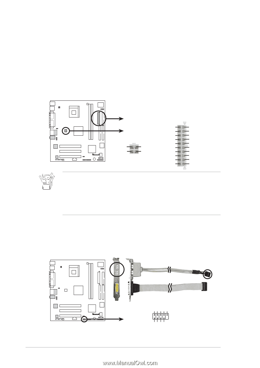
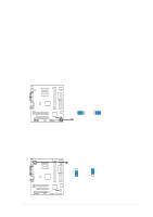
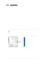
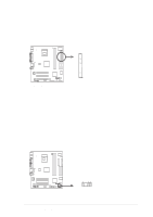
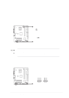
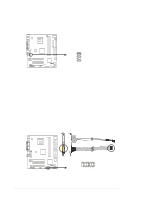
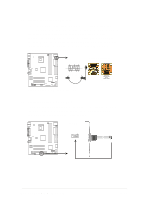
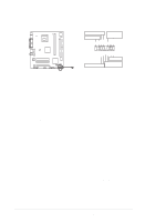
4. ATX power connectors (20-pin ATX_POWER1) These connectors connect to an ATX 12V power supply. The plugs from the power supply are designed to fit these connectors in only one orientation. Find the proper orientation and push down firmly until the connectors completely fit. In addition to the 20-pin ATXPWR connector, this motherboard requires that you connect the 4-pin ATX +12V power plug to provide sufficient power to the CPU. ATX_POWER1 Pin 1 +12.0VDC +5VSB ATX12V1 PWR_OK COM P4BGV-MX +12V DC GND +12V DC GND +5.0VDC COM +5.0VDC COM +3.3VDC P4BGV-MX ATX Power Connectors +3.3VDC +5.0VDC +5.0VDC -5.0VDC COM COM COM PS_ON# COM -12.0VDC +3.3VDC If you will need to replace the power supply in the future, make sure that your new ATX 12V power supply can provide 8A on the +12V lead and at least 1A on the +5-volt standby lead (+5VSB). The minimum recommended wattage is 230W, or 300W for a fully configured system. The system may become unstable and may experience difficulty powering up if the power supply is inadequate. 5. USB headers (10-1 pin USB1) USB1 is for the internal USB header that you can connect to the front USB ports. USB+5V LDM5 LDP5 GND NC P4BGV-MX P4BGV-MX USB 2.0 Header USB1 1 USB+5V LDM6 LDP6 GND 1-14 Chapter 1: Motherboard Information
-
 1
1 -
2
-
3
-
4
-
5
-
6
-
7
-
8
-
9
-
10
-
11
-
12
-
13
-
14
-
15
-
16
-
17
-
18
-
 19
19 -
 20
20 -
 21
21 -
 22
22 -
 23
23 -
 24
24 -
 25
25 -
 26
26 -
 27
27 -
 28
28 -
 29
29 -
30
-
31
-
32
-
33
-
34
-
35
-
36
-
37
-
38
-
39
-
40
-
41
-
42
-
43
-
44
-
45
-
46
-
47
-
48
-
49
-
50
-
51
-
52
-
53
-
54
-
55
-
56
-
57
-
58
-
59
-
60
 |
 |