Asus P4SGL-MX P4SGL-MX User Manual - Page 14
integrates the AC'97 Interface, four Universal Serial Bus Host controllers - bios
 |
View all Asus P4SGL-MX manuals
Add to My Manuals
Save this manual to your list of manuals |
Page 14 highlights
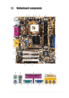
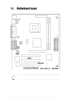
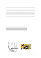
1 ATX 12V connector. This power connector connects the 4-pin 12V plug from the ATX 12V power supply. 2 DIP Switches. This 3-switch Dual Inline Package (DIP) allows you to set the CPU external frequency. 3 CPU Sockets. A 478-pin surface mount, Zero Insertion Force (ZIF) socket for the Intel® Pentium® 4 P478 Willamette & Northwood Processor with 100 MHz system bus that allows 1.4 GHz ~ 2.6 GHz plus of core frequency. 4 NorthBridge Controller. This SIS SIS650GL controller integrates a high performance host interface for the Intel® Pentium® 4 processor, a memory controller and an integrated graphics interface. 5 ATX power connector. This standard 20-pin connector connects to an ATX 12V power supply. The power supply must have at least 1A on the +5V standby lead (+5VSB). 6 DDR DIMM Sockets. These two 184-pin DIMM sockets support up to 2GB using non-ECC PC2100/1600 DDR SDRAM DIMMs with 2.1GBytes/sec of transfer rate. 7 IDE Connectors. These dual-channel bus master IDE connectors support up to four Ultra DMA133/100/66, PIO Modes 3 & 4 IDE devices. Both the primary(blue) and secondary(black) connectors are slotted to prevent incorrect insertion of the IDE ribbon cable. 8 AGP Slot. This Accelerated Graphics Port (AGP) slot only supports 1.5V AGP4X mode graphics cards for 3D graphical applications. 9 South bridge controller. This SIS SIS962L0 MuTIOL Media I/O controller integrates the AC'97 Interface, four Universal Serial Bus Host controllers, two IDE Master/Slave controllers, Flash BIOS, and PCI bus for three PCI Slots. 10 Onboard LED. This onboard LED lights up if there is a standby power on the motherboard. This LED acts as a reminder to turn off the system power before plugging or unplugging devices. 11 Floppy Disk connector. This connector connects the provided ribbon cable for the floppy disk drive. One side of the connector is slotted to prevent incorrect insertion of the floppy disk cable. 12 COM2 connector. This 9-pin connector connects to a COM2 port. 13 Flash ROM. This 2MB firmware contains the programmable BIOS program. 1-4 Chapter 1: Motherboard Information
-
 1
1 -
2
-
3
-
4
-
5
-
6
-
7
-
8
-
 9
9 -
 10
10 -
 11
11 -
 12
12 -
 13
13 -
 14
14 -
 15
15 -
 16
16 -
 17
17 -
 18
18 -
 19
19 -
20
-
21
-
22
-
23
-
24
-
25
-
26
-
27
-
28
-
29
-
30
-
31
-
32
-
33
-
34
-
35
-
36
-
37
-
38
-
39
-
40
-
41
-
42
-
43
-
44
-
45
-
46
-
47
-
48
-
49
-
50
-
51
-
52
-
53
-
54
-
55
-
56
-
57
-
58
-
59
-
60
-
61
-
62
-
63
-
64
 |
 |
