Asus P4SP-MX SE P4SP-MX SE English User Manual E1676a - Page 25
Connectors - vga
 |
View all Asus P4SP-MX SE manuals
Add to My Manuals
Save this manual to your list of manuals |
Page 25 highlights
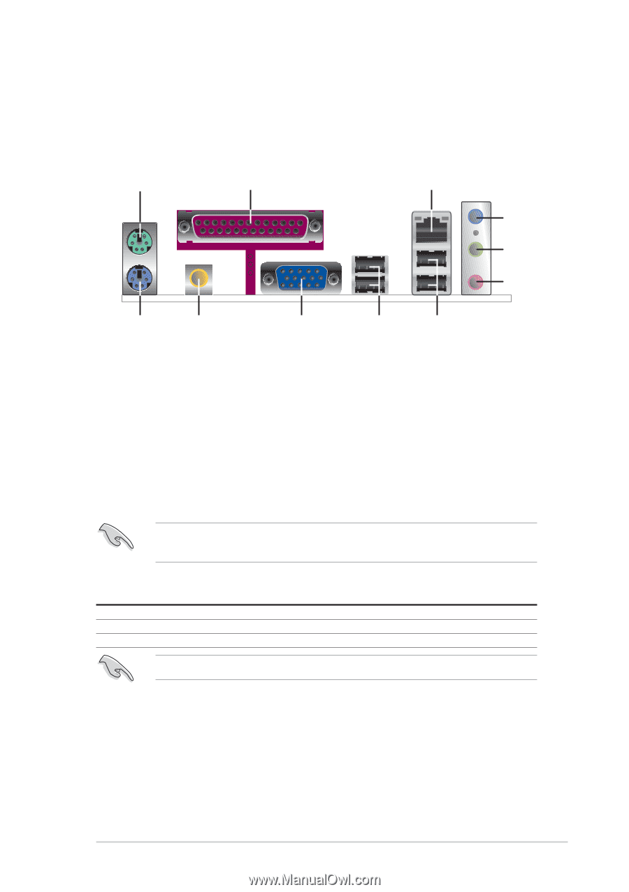
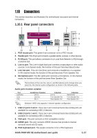
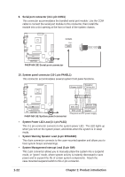
1.10 Connectors This section describes and illustrates the motherboard rear panel and internal connectors. 1.10.1 Rear panel connectors 1 2 3 4 5 6 11 10 9 8 7 1. PS/2 mouse port. This green 6-pin connector is for a PS/2 mouse. 2. Parallel port. This 25-pin port connects a parallel printer, scanner, or other devices. 3. RJ-45 port. This port allows connection to a Local Area Network (LAN) through a network hub. 4. Line In port. This Line In (light blue) port connects a tape player or other audio sources. In 6-channel mode, the function of this port becomes Bass/Center. 5. Line Out port. This Line Out (lime) port connects a headphone or a speaker. In 4/6-channel mode, the function of this port becomes Front Speaker Out. 6. Microphone port. This Mic (pink) port connects a microphone. In 4/6-channel mode, the function of this port becomes Rear Speaker Out. The functions of the Line Out, Line In, and Microphone ports change when you select the 4/6-channel audio configuration as shown in the following table. Audio ports function variation Port Light Blue Lime Pink Headphone /2-Speaker Line In Line Out Mic In 4-Speaker Line In Front Speaker Out Rear Speaker Out 6-Speaker Bass/Center Front Speaker Out Rear Speaker Out Windows® 98SE only supports 2-channel speaker configuration. 7. USB 2.0 ports 3 and 4. These two 4-pin Universal Serial Bus (USB) ports are available for connecting USB 2.0 devices. 8. USB 2.0 ports 1 and 2. These two 4-pin Universal Serial Bus (USB) ports are available for connecting USB 2.0 devices. 9. VGA port. This port connects a VGA compatible monitor. 10. S/PDIF port. This port connects S/PDIF devices that provide 6-channel surround sound and 3D audio. 11. PS/2 keyboard port. This purple connector is for a PS/2 keyboard. ASUS P4SP-MX SE motherboard user guide 1-17
-
 1
1 -
2
-
3
-
4
-
5
-
6
-
7
-
8
-
9
-
10
-
11
-
12
-
13
-
14
-
15
-
16
-
17
-
18
-
19
-
 20
20 -
 21
21 -
 22
22 -
 23
23 -
 24
24 -
 25
25 -
 26
26 -
 27
27 -
 28
28 -
 29
29 -
 30
30 -
31
-
32
-
33
-
34
-
35
-
36
-
37
-
38
-
39
-
40
-
41
-
42
-
43
-
44
-
45
-
46
-
47
-
48
-
49
-
50
-
51
-
52
-
53
-
54
-
55
-
56
-
57
-
58
-
59
-
60
-
61
-
62
-
63
-
64
 |
 |