Asus P4SP-MX SE P4SP-MX SE English User Manual E1676a - Page 30
System Power LED Lead 3-1 pin PLED - mx serial
 |
View all Asus P4SP-MX SE manuals
Add to My Manuals
Save this manual to your list of manuals |
Page 30 highlights
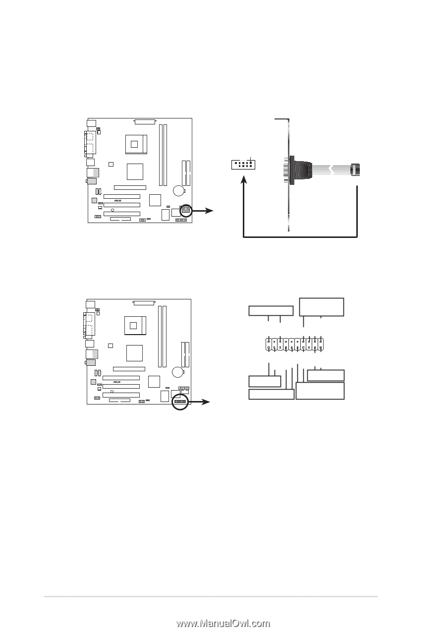
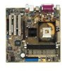
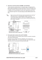
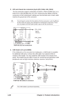
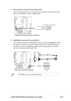
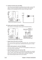
9. Serial port connector (10-1 pin COM1) This connector accommodates the bundled serial port module. Use the COM cable to connect the serial port module to this connector, then install the module into a slot opening at the front or back of the system chassis. COM1 PIN 1 ® P4SP-MX SE P4SP-MX SE Serial port connector 10. System panel connector (10-1 pin PANEL1) This connector accommodates several system front panel functions. Speaker Power LED Connector PLED+ PLED+5V Ground Ground Speaker +5 V IDELED ExtSMI# Ground PWR Ground Reset Ground ® P4SP-MX SE P4SP-MX SE System panel connector IDE LED SMI Lead Reset SW ATX Power Switch* * Requires an ATX power supply. • System Power LED Lead (3-1 pin PLED) This 3-1 pin connector connects to the system power LED. The LED lights up when you turn on the system power, and blinks when the system is in sleep mode. • System Warning Speaker Lead (4-pin SPEAKER) This 4-pin connector connects to the case-mounted speaker and allows you to hear system beeps and warnings. • System Management Interrupt Lead (2-pin SMI) This 2-pin connector allows you to manually place the system into a suspend mode, or "green" mode, where system activity is instantly decreased to save power and to expand the life of certain system components. Attach the case-mounted suspend switch to this 2-pin connector. 1-22 Chapter 1: Product introduction
-
 1
1 -
2
-
3
-
4
-
5
-
6
-
7
-
8
-
9
-
10
-
11
-
12
-
13
-
14
-
15
-
16
-
17
-
18
-
19
-
20
-
21
-
22
-
23
-
24
-
 25
25 -
 26
26 -
 27
27 -
 28
28 -
 29
29 -
 30
30 -
 31
31 -
 32
32 -
 33
33 -
 34
34 -
 35
35 -
36
-
37
-
38
-
39
-
40
-
41
-
42
-
43
-
44
-
45
-
46
-
47
-
48
-
49
-
50
-
51
-
52
-
53
-
54
-
55
-
56
-
57
-
58
-
59
-
60
-
61
-
62
-
63
-
64
 |
 |