Asus P4V533-MX P4V533-MX User Manual - Page 27
Connectors
 |
View all Asus P4V533-MX manuals
Add to My Manuals
Save this manual to your list of manuals |
Page 27 highlights
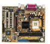
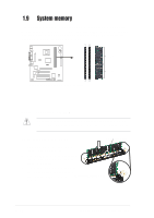
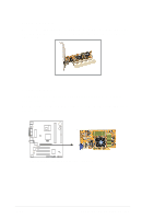
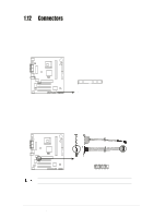
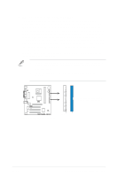
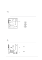
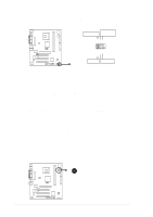
1.12 Connectors This section describes and illustrates the internal connectors on the motherboard. 1. Floppy disk drive connector (34-1 pin FLOPPY1) This connector supports the provided floppy drive ribbon cable. After connecting one end to the motherboard, connect the other end to the floppy drive. (Pin 5 is removed to prevent incorrect insertion when using ribbon cables with pin 5 plug). ® FLOPPY1 P4V533-MX PIN 1 NOTE: Orient the red markings on the floppy ribbon cable to PIN 1. P4V533-MX Floppy Disk Drive Connector 2. GAME/MIDI connector (16-1 pin GAME1) This connector supports a GAME/MIDI module. Connect the GAME/MIDI cable with yellow connector to the yellow header onboard. The GAME/MIDI port on the module connects a joystick or a game pad for playing games, and MIDI devices for playing or editing audio files. +5V J2B1 J2CX MIDI_OUT J2CY J2B2 MIDI_IN ® P4V533-MX P4V533-MX Smartcard GAME1 The GAME/MIDI module is purchased separately. +5V J1B1 J1CX GND GND J1CY J1B2 +5V ASUS P4V533-MX motherboard user guide 1-17
-
 1
1 -
2
-
3
-
4
-
5
-
6
-
7
-
8
-
9
-
10
-
11
-
12
-
13
-
14
-
15
-
16
-
17
-
18
-
19
-
20
-
21
-
 22
22 -
 23
23 -
 24
24 -
 25
25 -
 26
26 -
 27
27 -
 28
28 -
 29
29 -
 30
30 -
 31
31 -
 32
32 -
33
-
34
-
35
-
36
-
37
-
38
-
39
-
40
-
41
-
42
-
43
-
44
-
45
-
46
-
47
-
48
-
49
-
50
-
51
-
52
-
53
-
54
-
55
-
56
-
57
-
58
-
59
-
60
 |
 |