Asus P4V533-MX P4V533-MX User Manual - Page 28
IDE connectors 40-1 pin PRI_IDE, SEC_IDE
 |
View all Asus P4V533-MX manuals
Add to My Manuals
Save this manual to your list of manuals |
Page 28 highlights
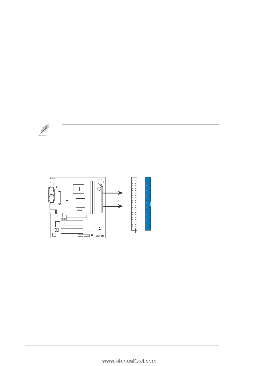
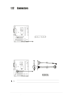
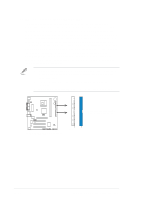
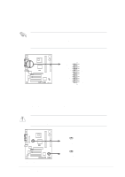
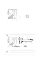
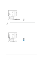
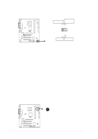
3. IDE connectors (40-1 pin PRI_IDE, SEC_IDE) This connector supports the provided UltraDMA133/100 IDE ribbon cable. Connect the cable's blue connector to the primary (recommended) or secondary IDE connector, then connect the gray connector to the UltraDMA133/100 slave device (hard disk drive) and the black connector to the UltraDMA133/100 master device. It is recommended that you connect non-UltraDMA133/100 devices to the secondary IDE connector. If you install two hard disks, you must configure the second drive as a slave device by setting its jumper accordingly. Refer to the hard disk documentation for the jumper settings. BIOS supports specific device bootup. If you have more than two UltraDMA133/100 devices, purchase another UltraDMA133/100 cable. You may configure two hard disks to be both master devices with two ribbon cables - one for the primary IDE connector and another for the secondary IDE connector. 1. Pin 20 on each IDE connector is removed to match the covered hole on the UltraDMA cable connector. This prevents incorrect orientation when you connect the cables. 2. The hole near the blue connector on the UltraDMA133/100/66 cable is intentional. 3. For UltraDMA133/100/66 IDE devices, use the 80-conductor IDE cable. SEC_IDE PRI_IDE ® P4V533-MX NOTE: Orient the red markings on the IDE ribbon cable to PIN 1 P4V533-MX IDE Connectors PIN 1 PIN 1 1-18 Chapter 1: Product introduction
-
 1
1 -
2
-
3
-
4
-
5
-
6
-
7
-
8
-
9
-
10
-
11
-
12
-
13
-
14
-
15
-
16
-
17
-
18
-
19
-
20
-
21
-
22
-
 23
23 -
 24
24 -
 25
25 -
 26
26 -
 27
27 -
 28
28 -
 29
29 -
 30
30 -
 31
31 -
 32
32 -
 33
33 -
34
-
35
-
36
-
37
-
38
-
39
-
40
-
41
-
42
-
43
-
44
-
45
-
46
-
47
-
48
-
49
-
50
-
51
-
52
-
53
-
54
-
55
-
56
-
57
-
58
-
59
-
60
 |
 |