Asus P5AD2-E P5AD2-E User's Manual for English Edition
Asus P5AD2-E Manual
 |
View all Asus P5AD2-E manuals
Add to My Manuals
Save this manual to your list of manuals |
Asus P5AD2-E manual content summary:
- Asus P5AD2-E | P5AD2-E User's Manual for English Edition - Page 1
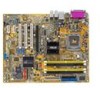
P5AD2-E Motherboard - Asus P5AD2-E | P5AD2-E User's Manual for English Edition - Page 2
Product warranty or service will not be extended if: (1) the product is repaired, modified or altered, unless such repair, modification of alteration is authorized in writing by ASUS; or (2) the serial number of the product is defaced or missing. ASUS PROVIDES THIS MANUAL "AS IS" WITHOUT WARRANTY - Asus P5AD2-E | P5AD2-E User's Manual for English Edition - Page 3
2-2 2.2.2 Screw holes 2-2 2.2.3 Motherboard layout 2-3 2.2.4 Layout contents 2-4 2.3 Central Processing Unit (CPU 2-6 2.3.1 Installing the CPU 2-6 2.3.2 Installing the CPU heatsink and fan 2-9 2.3.3 Uninstalling the CPU heatsink and fan 2-11 2.4 System memory 2-13 2.4.1 Overview 2-13 - Asus P5AD2-E | P5AD2-E User's Manual for English Edition - Page 4
BIOS 2 utility 3-5 3.1.4 ASUS EZ Flash utility 3-7 3.1.5 ASUS Update utility 3-8 3.2 BIOS setup program 3-11 3.2.1 BIOS menu screen 3-12 3.2.2 Menu bar 3-12 3.2.3 Navigation keys 3-12 3.2.4 Menu items 3-13 3.2.5 Sub-menu items 3-13 3.2.6 Configuration fields 3-13 3.2.7 Pop-up window - Asus P5AD2-E | P5AD2-E User's Manual for English Edition - Page 5
the support CD 4-1 4.2.2 Drivers menu 4-2 4.2.3 Utilities menu 4-3 4.2.4 Manuals menu 4-5 4.2.5 Contact information 4-5 4.2.6 Other information 4-6 4.3 Software information 4-8 4.3.1 ASUS MyLogo2 4-8 4.3.2 AI NET2 4-10 4.3.3 C-Media 3D audio configuration 4-11 Appendix: CPU - Asus P5AD2-E | P5AD2-E User's Manual for English Edition - Page 6
. This equipment generates, uses and can radiate radio frequency energy and, if not installed and used in accordance with manufacturer's instructions, may cause harmful interference to radio communications. However, there is no guarantee that interference will not occur in a particular installation - Asus P5AD2-E | P5AD2-E User's Manual for English Edition - Page 7
qualified service technician or your retailer. Operation safety • Before installing the motherboard and adding devices on it, carefully read all the manuals stable surface. • If you encounter technical problems with the product, contact a qualified service technician or your retailer. This symbol of - Asus P5AD2-E | P5AD2-E User's Manual for English Edition - Page 8
describes the CPU features and technologies that the motherboard supports. Where to find more information Refer to the following sources for additional information and for product and software updates. 1. ASUS websites The ASUS website provides updated information on ASUS hardware and software - Asus P5AD2-E | P5AD2-E User's Manual for English Edition - Page 9
following symbols used throughout this manual. D A N G E R / W A R N I N G : Information to prevent injury to yourself when trying to complete a task. C A U T I O N : Information to prevent damage to the components when trying to complete a task. I M P O R T A N T : Instructions that you MUST follow - Asus P5AD2-E | P5AD2-E User's Manual for English Edition - Page 10
(EIST) (Note: Due to chipset limitation, P5AD2-E doesn't support Intel Dual-core CPU or 65nm CPU) Northbridge: Intel® 925XE Memory Controller Hub (MCH) Southbridge: Intel® ICH6 1066/800/533 MHz Dual-channel memory architecture 4 x 240-pin DIMM sockets support unbufferred non-ECC DDR2-711 (FSB 1066 - Asus P5AD2-E | P5AD2-E User's Manual for English Edition - Page 11
channel audio ports 1 x Floppy disk drive connector 1 x CPU fan connector 1 x Power fan connector 2 x Chassis fan connector 1 x CD audio-in connector 1 x Front panel Audio connector 2 x USB 2.0 connectors support drivers ASUS PC Probe ASUS Update Anti-virus software (OEM version) ASUS AI Booster ASUS - Asus P5AD2-E | P5AD2-E User's Manual for English Edition - Page 12
xii - Asus P5AD2-E | P5AD2-E User's Manual for English Edition - Page 13
This chapter describes the motherboard features and the new technologies it supports. 1Product introduction - Asus P5AD2-E | P5AD2-E User's Manual for English Edition - Page 14
Chapter summary 1 1.1 Welcome 1-1 1.2 Package contents 1-1 1.3 Special features 1-2 ASUS P5AD2-E - Asus P5AD2-E | P5AD2-E User's Manual for English Edition - Page 15
for the following items. Motherboard ASUS P5AD2-E motherboard Cables 1 x Serial ATA signal cables 1 x Serial ATA power cables 1 x Ultra DMA/133 cables 1 X Floppy disk drive cable Accessories Application CDs Documentation I/O shield ASUS motherboard support CD User guide If any of the above - Asus P5AD2-E | P5AD2-E User's Manual for English Edition - Page 16
, dual-channel memory, and PCI Express interfaces. The Intel® ICH6 Southbridge represents the sixth generation I/O controller hub that provides the interface for the storage, I/O, PCI Express, and 8-channel high definition audio interfaces. DDR2 memory support The motherboard supports DDR2 memory - Asus P5AD2-E | P5AD2-E User's Manual for English Edition - Page 17
plugging status of each jack, impedance sensing to determine audio device classes, and pre-defined equalization for various audio devices. See pages 2-22 to 2-23, and page 4-11 for details. S/PDIF digital sound ready The motherboard supports the S/PDIF technology through the S/PDIF interfaces on the - Asus P5AD2-E | P5AD2-E User's Manual for English Edition - Page 18
time between the CPU and the system memory. Enabling Hyper Path 2 on systems with the Intel® PAT improves memory performance without affecting system stability. See the Appendix for details. Native DDR2-711/600 support This motherboard offers native DDR2-711/600 memory support to ensure superior - Asus P5AD2-E | P5AD2-E User's Manual for English Edition - Page 19
to the system loading to ensure quiet, cool, and efficient operation. See pages 3-36 to 3-37 for details. ASUS MyLogo2™ This new feature present in the motherboard allows you to personalize and add style to your system with customizable boot logos. See page 4-8 for details. ASUS P5AD2-E 1-5 - Asus P5AD2-E | P5AD2-E User's Manual for English Edition - Page 20
1-6 Chapter 1: Product introduction - Asus P5AD2-E | P5AD2-E User's Manual for English Edition - Page 21
This chapter lists the hardware setup procedures that you have to perform when installing system components. It includes description of the jumpers and connectors on the motherboard. 2 Hardware information - Asus P5AD2-E | P5AD2-E User's Manual for English Edition - Page 22
Chapter summary 2 2.1 Before you proceed 2-1 2.2 Motherboard overview 2-2 2.3 Central Processing Unit (CPU 2-6 2.4 System memory 2-13 2.5 Expansion slots 2-17 2.6 Jumpers 2-20 2.7 Connectors 2-22 ASUS P5AD2-E - Asus P5AD2-E | P5AD2-E User's Manual for English Edition - Page 23
. This is a reminder that you should shut down the system and unplug the power cable before removing or plugging in any motherboard component. The illustration below shows the location of the onboard LED. P5AD2-E ® P5AD2-E Onboard LED SB_PWR1 ON Standby Power OFF Powered Off ASUS P5AD2-E 2-1 - Asus P5AD2-E | P5AD2-E User's Manual for English Edition - Page 24
or removing the motherboard. Failure to do so can cause you physical injury and damage motherboard components. 2.2.1 Placement direction When installing the motherboard, make sure indicated by circles to secure the motherboard to the chassis. Do not overtighten the screws! Doing so can damage the - Asus P5AD2-E | P5AD2-E User's Manual for English Edition - Page 25
Motherboard layout 24.5cm (9.6in) MS1 KBPWR1 KB1 ATX12V1 LGA775 CPU_FAN1 Super I/O PARALLEL PORT FLOPPY1 DDR2 DIMM_B1 (64 bit,240-pin module) DDR2 DIMM_B2 (64 bit,240-pin module) P5AD2-E DDR2 DIMM_A1 (64 bit,240-pin module) DDR2 DIMM_A2 (64 bit CHA_FAN1 GAME1 PANEL1 ASUS P5AD2-E 2-3 - Asus P5AD2-E | P5AD2-E User's Manual for English Edition - Page 26
2.2.4 Layout contents Slots 1. DDR2 DIMM slots 2. PCI slots 3. PCI Express slot Jumpers 1. Clear RTC RAM (3-pin CLRTC1) 2. USB Device wake-up (3-pin USBPW12, USBPW34, USBPW56, USBPW78) 3. Keyboard power (3-pin KBPWR1) Rear panel connectors 1. Parallel port 2. LAN (RJ-45) port 3. Rear Speaker Out - Asus P5AD2-E | P5AD2-E User's Manual for English Edition - Page 27
audio connector (10-1 pin AAFP) 6. USB connectors (10-1 pin USB56, USB78) 7. Serial port connector (10-1 pin COM1) 8. GAME/MIDI port connector (16-1 pin GAME1) 9. Chassis intrusion connector (4-1 pin CHASSIS1) 10. CPU Page 2-24 2-24 2-25 2-26 2-26 2-27 2-27 2-28 2-28 2-29 2-30 2-31 ASUS P5AD2-E 2-5 - Asus P5AD2-E | P5AD2-E User's Manual for English Edition - Page 28
to the socket contacts resulting from incorrect CPU installation/removal, or misplacement/loss/incorrect removal of the PnP cap. 2.3.1 Installing the CPU To install a CPU: 1. Locate the CPU socket on the motherboard. ® P5AD2-E Socket 775 Before installing the CPU, make sure that the cam box is - Asus P5AD2-E | P5AD2-E User's Manual for English Edition - Page 29
cap B from the load plate window to remove (B). Load plate 5. Position the CPU over the socket, making sure that the gold triangle is on the bottom-left corner of the socket. The socket alignment A l i g n m e n t k e y key should fit into the CPU notch. Gold triangle mark ASUS P5AD2-E A 2-7 - Asus P5AD2-E | P5AD2-E User's Manual for English Edition - Page 30
on the socket and damaging the CPU! 6. Close the load plate (A), then A push the load lever (B) until it snaps into the retention tab. B The motherboard supports Intel® Pentium® 4 LGA775 processors with the Intel® Enhanced Memory 64 Technology (EM64T), Enhanced Intel SpeedStep® Technology - Asus P5AD2-E | P5AD2-E User's Manual for English Edition - Page 31
heatsink and fan assembly such that the CPU fan cable is closest to the CPU fan connector. Narrow end of the groove Motherboard hole Fastener Make sure to orient each fastener with the narrow end of the groove pointing outward. (The photo shows the groove shaded for emphasis.) ASUS P5AD2-E 2-9 - Asus P5AD2-E | P5AD2-E User's Manual for English Edition - Page 32
fan B assembly in place. A A A B B B A 3. Connect the CPU fan cable to the connector on the motherboard labeled CPU_FAN1. CPU_FAN1 ® P5AD2-E GND CPU FAN PWR CPU FAN IN CPU FAN PWM P5AD2-E CPU fan connector Do not forget to connect the CPU fan connector! Hardware monitoring errors can - Asus P5AD2-E | P5AD2-E User's Manual for English Edition - Page 33
on the motherboard. 2. Rotate each fastener counterclockwise. 3. Pull up two fasteners at a time in a diagonal sequence to disengage the heatsink and fan B assembly from the A motherboard. A B A B B A 4. Carefully remove the heatsink and fan assembly from the motherboard. ASUS P5AD2 - Asus P5AD2-E | P5AD2-E User's Manual for English Edition - Page 34
after resetting. (The photo shows the groove shaded for emphasis.) Narrow end of the groove Refer to the documentation in the boxed or stand-alone CPU fan package for detailed information on CPU fan installation. 2-12 Chapter 2: Hardware information - Asus P5AD2-E | P5AD2-E User's Manual for English Edition - Page 35
on the next page for details. • Due to chipset resource allocation, the system may detect less than 4 GB system memory when you installed four 1 GB DDR2 memory modules. • This motherboard does not support memory modules made up of 128 Mb chips or double sided x16 memory modules. ASUS P5AD2-E 2-13 - Asus P5AD2-E | P5AD2-E User's Manual for English Edition - Page 36
into either the yellow slots or the black slots as one pair of Dual-channel memory configuration. C - Supports two pairs of modules inserted into the yellow and black slots as two pairs of Dual-channel memory configuration. Visit the ASUS website for the latest DDR2-711 MHz (FSB 1066)/ DDR2-600 MHz - Asus P5AD2-E | P5AD2-E User's Manual for English Edition - Page 37
DDR2-533 Size Vendor Model B r a n d Side(s) Component DIMM support ABC 256 MB ELPIDA EBE25UC8AAFV-DF-E N/A SS E2508AA-DF-E ••• 512 MB AD29608A8A-375D • • • 256 MB Ballistix BL3264AA53V.8FB N/A SS N/A ••• 512 MB Ballistix BL6464AA53V.16FB N/A DS N/A ••• ASUS P5AD2-E 2-15 - Asus P5AD2-E | P5AD2-E User's Manual for English Edition - Page 38
components. Failure to do so can cause severe damage to both the motherboard and the components. To install a DIMM: 1. Unlock a DIMM socket into a socket to avoid damaging the DIMM. • The DDR2 DIMM sockets do not support DDR DIMMs. DO not install DDR DIMMs to the DDR2 DIMM sockets. 2.4.4 Removing - Asus P5AD2-E | P5AD2-E User's Manual for English Edition - Page 39
cover (if your motherboard is already installed in drivers support "Share IRQ" or that the cards do not need IRQ assignments. Otherwise, conflicts will arise between the two PCI groups, making the system unstable and the card inoperable. Refer to the table on the next page for details. ASUS P5AD2 - Asus P5AD2-E | P5AD2-E User's Manual for English Edition - Page 40
Compatible Mouse Port* Numeric Data Processor Primary IDE Channel Secondary IDE Channel * These IRQs are usually available for ISA or PCI devices. IRQ assignments for this motherboard Onboard SATA port - shared - - - - - - Onboard Azalia audio shared Onboard LAN1 - shared - - - - - - 2-18 - Asus P5AD2-E | P5AD2-E User's Manual for English Edition - Page 41
card installed on the PCI Express x16 slot. 2.5.6 PCI Express x1 slot This motherboard supports PCI Express x1 network cards, SCSI cards and other cards that comply with the PCI Express specifications. The following figure shows a network card installed on the PCI Express x1 slot. ASUS P5AD2-E 2-19 - Asus P5AD2-E | P5AD2-E User's Manual for English Edition - Page 42
the CMOS memory of date, P5AD2-E Clear RTC RAM CLRTC1 12 23 Normal (Default) Clear CMOS You do not need to clear the RTC when the system hangs due to overclocking. For system failure due to overclocking, use the C.P.R. (CPU Parameter Recall) feature. Shut down and reboot the system so the BIOS - Asus P5AD2-E | P5AD2-E User's Manual for English Edition - Page 43
Set to +5VSB to wake up from S3 and S4 sleep modes (no power to CPU, DRAM in slow refresh, power supply in reduced power mode). The USBPWR12 and USBPWR34 and a corresponding setting in the BIOS. KBPWR1 12 23 P5AD2-E +5V +5VSB (Default) ® P5AD2-E Keyboard power setting ASUS P5AD2-E 2-21 - Asus P5AD2-E | P5AD2-E User's Manual for English Edition - Page 44
port connects the rear speakers on a 4-channel, 6-channel, or 8-channel audio configuration. 4 . S i d e S p e a k e r O u t p o r t ( b l a c k ) . This port connects the side speakers in an 8-channel audio configuration. 5 . L i n e I n p o r t ( l i g h t b l u e ) . This port connects a tape, CD - Asus P5AD2-E | P5AD2-E User's Manual for English Edition - Page 45
a l S / P D I F O u t p o r t . This port connects an external audio output device via a coaxial S/PDIF cable. 1 2 . P S / 2 k e y b o a r d p o r t ( p u r p l e ) . This port is for a PS/2 keyboard. 1 3 . P S / 2 m o u s e p o r t ( g r e e n ) . This port is for a PS/2 mouse. ASUS P5AD2-E 2-23 - Asus P5AD2-E | P5AD2-E User's Manual for English Edition - Page 46
to PIN 1. ® P5AD2-E Floppy disk drive connector 2 . Primary IDE connector (40-1 pin PRI_IDE1) This connector is for an Ultra DMA 100/66 signal cable. The Ultra DMA 100/66 signal cable has three connectors: a blue connector for the primary IDE connector on the motherboard, a black connector for - Asus P5AD2-E | P5AD2-E User's Manual for English Edition - Page 47
RSATA_TXP1 RSATA_TXN1 GND RSATA_RXP1 RSATA_RXN1 GND P5AD2-E SATA connectors Important notes on Serial ATA • You must install Windows® 2000 Service Pack 4 or the Windows® XP Service Pack 1 before using Serial ATA /SATA2 SATA3/SATA4 Red Black Master Slave Boot disk Data disk ASUS P5AD2-E 2-25 - Asus P5AD2-E | P5AD2-E User's Manual for English Edition - Page 48
P5AD2-E Right Audio Channel Ground Ground Left Audio Channel ® CD P5AD2-E CD audio connector Enable the CD-IN function in the audio utility when using this connector. 5 . Front panel audio connector (10-1 pin AAFP) This connector is for a chassis-mounted front panel audio I/O module that supports - Asus P5AD2-E | P5AD2-E User's Manual for English Edition - Page 49
These USB connectors comply with USB 2.0 specification that supports up to 480 Mbps connection speed. P5AD2-E ® USB+5V USB_P8USB_P8+ GND NC USB+5V GND P5AD2-E USB 2.0 connectors USB56 1 USB78 1 Never connect a 1 3 9 4 c a b l e to the USB connectors. Doing so will damage the motherboard! The - Asus P5AD2-E | P5AD2-E User's Manual for English Edition - Page 50
a joystick or game pad for playing games, and MIDI devices for playing or editing audio files. P5AD2-E ® +5V J1B2 J1CY GND GND J1CX J1B1 +5V MIDI_IN J2B2 J2CY MIDI_OUT J2CX J2B1 +5V P5AD2-E GAME connector GAME1 The GAME/MIDI cable is purchased separately. 9 . Chassis intrusion connector - Asus P5AD2-E | P5AD2-E User's Manual for English Edition - Page 51
caps on the fan connectors! CPU_FAN1 GND CPU FAN PWR CPU FAN IN CPU FAN PWM P5AD2-E GND +12V Rotation PWR_FAN1 ® P5AD2-E Fan connectors CHA_FAN1 Rotation +12V GND CHA_FAN2 GND +12V Rotation Only the CPU_FAN1 and CHA_FAN1 connectors support the ASUS Q-Fan 2 feature. ASUS P5AD2-E 2-29 - Asus P5AD2-E | P5AD2-E User's Manual for English Edition - Page 52
has been tested to support the motherboard power requirements with the following configuration: CPU : Memory : Graphics card : power rating if you intend to install additional devices. P5AD2-E ATX12V1 GND +12V DC GND +12V DC ® P5AD2-E ATX power connectors EATXPWR1 +3 Volts +12 Volts - Asus P5AD2-E | P5AD2-E User's Manual for English Edition - Page 53
depending on the BIOS settings. Pressing the power switch for more than four seconds while the system is ON turns the system OFF. • Reset button (Blue 2-pin RESET) This 2-pin connector is for the chassis-mounted reset button for system reboot without turning off the system power. ASUS P5AD2-E 2-31 - Asus P5AD2-E | P5AD2-E User's Manual for English Edition - Page 54
2-32 Chapter 2: Hardware information - Asus P5AD2-E | P5AD2-E User's Manual for English Edition - Page 55
This chapter tells how to change the system settings through the BIOS Setup menus. Detailed descriptions of the BIOS parameters are also provided. 3 BIOS setup - Asus P5AD2-E | P5AD2-E User's Manual for English Edition - Page 56
Chapter summary 3 3.1 Managing and updating your BIOS 3-1 3.2 BIOS setup program 3-11 3.3 Main menu 3-14 3.4 Advanced menu 3-19 3.5 Power menu 3-33 3.6 Boot menu 3-38 3.7 Exit menu 3-43 ASUS P5AD2-E - Asus P5AD2-E | P5AD2-E User's Manual for English Edition - Page 57
motherboard BIOS using the ASUS Update or AFUDOS utilities. 3.1.1 Creating a bootable floppy disk 1. Do either one of the following to create a bootable floppy disk. DOS environment a. Insert a 1.44MB floppy disk into the drive. b. At the DOS prompt, type format A:/S then press . Windows® XP - Asus P5AD2-E | P5AD2-E User's Manual for English Edition - Page 58
optical drive letter. e. Press , then follow screen instructions to continue. 2. Copy the original or the latest motherboard BIOS file to the bootable floppy disk. 3.1.2 AFUDOS utility The AFUDOS utility allows you to update the BIOS file in DOS environment using a bootable floppy disk with - Asus P5AD2-E | P5AD2-E User's Manual for English Edition - Page 59
(afudos.exe) from the motherboard support CD to the bootable floppy disk you created earlier. 3. Boot the system in DOS mode, then at the prompt type: afudos /i[filename] where [filename] is the latest or the original BIOS file on the bootable floppy disk. A:\>afudos /iP5AD2EB.rom ASUS P5AD2-E 3-3 - Asus P5AD2-E | P5AD2-E User's Manual for English Edition - Page 60
system boot failure! 5. The utility returns to the DOS prompt after the BIOS update process is completed. Reboot the system from the hard disk drive. A:\>afudos /iP5AD2E.rom AMI Firmware Update Utility - Version 1.19(ASUS V2.07(03.11.24BB)) Copyright (C) 2002 American Megatrends, Inc. All rights - Asus P5AD2-E | P5AD2-E User's Manual for English Edition - Page 61
2 utility The ASUS CrashFree BIOS 2 is an auto recovery tool that allows you to restore the BIOS file when it fails or gets corrupted during the updating process. You can update a corrupted BIOS file using the motherboard support CD or the floppy disk that contains the updated BIOS file. • Prepare - Asus P5AD2-E | P5AD2-E User's Manual for English Edition - Page 62
updating the BIOS! Doing so can cause system boot failure! 4. Restart the system after the utility completes the updating process. The recovered BIOS may not be the latest BIOS version for this motherboard. Visit the ASUS website (www.asus.com) to download the latest BIOS file. 3-6 Chapter 3: BIOS - Asus P5AD2-E | P5AD2-E User's Manual for English Edition - Page 63
+ during the Power-On Self Tests (POST). To update the BIOS using EZ Flash: 1. Visit the ASUS website (www.asus.com) to download the latest BIOS file for the motherboard and rename the same to P 5 A D 2 E B . R O M. 2. Save the BIOS file to a floppy disk, then restart the system. 3. Press - Asus P5AD2-E | P5AD2-E User's Manual for English Edition - Page 64
you to manage, save, and update the motherboard BIOS in Windows® environment. The ASUS Update utility allows you to: • Save the current BIOS file • Download the latest BIOS file from the Internet • Update the BIOS from an updated BIOS file • Update the BIOS directly from the Internet, and • View - Asus P5AD2-E | P5AD2-E User's Manual for English Edition - Page 65
U p d a t e. The ASUS Update main window appears. 2. Select U p d a t e B I O S f r o m 3. Select the ASUS FTP site t h e I n t e r n e t option from the nearest you to avoid network drop-down menu, then click traffic, or click A u t o S e l e c t. N e x t. Click N e x t. ASUS P5AD2-E 3-9 - Asus P5AD2-E | P5AD2-E User's Manual for English Edition - Page 66
to download. Click Next. 5. Follow the screen instructions to complete the update process. The ASUS Update utility is capable of updating itself through the Internet. Always update the utility to avail all its features. Updating the BIOS through a BIOS file To update the BIOS through a BIOS file - Asus P5AD2-E | P5AD2-E User's Manual for English Edition - Page 67
under the Exit Menu. See section "3.7 Exit Menu." • The BIOS setup screens shown in this section are for reference purposes only, and may not exactly match what you see on your screen. • Visit the ASUS website (www.asus.com) to download the latest BIOS file for this motherboard. ASUS P5AD2-E 3-11 - Asus P5AD2-E | P5AD2-E User's Manual for English Edition - Page 68
Slave IDE Configuration System Information [11:51:19] [Thu 05/07/2004] [1.44M, 3.5 in] [English] : [ST320413A] : [ASUS CD-S520/A] : [Not Detected] : [Not Detected] : [Not Detected] : [Not Detected] Use [ENTER], [TAB] or keys differ from one screen to another. 3-12 Chapter 3: BIOS setup - Asus P5AD2-E | P5AD2-E User's Manual for English Edition - Page 69
to malfunction. Configure DRAM Timing by SPD Memory Acceleration Mode DRAM Idle Timer DRAm Refresh 64 MB] [Enabled] ICH Delayed Transaction [Enabled] MPS Revision [1.4] Select Screen Select Item +- Change Option F1 General Help F10 Save and Exit ESC Exit Pop-up window Scroll bar ASUS P5AD2 - Asus P5AD2-E | P5AD2-E User's Manual for English Edition - Page 70
you an overview of the basic system information. Refer to section "3.2.1 BIOS menu screen" for information on the menu screen items and how to 11:51:19] [Thu 05/07/2004] [1.44M, 3.5 in] [English] : [ST320413A] : [ASUS CD-S520/A] : [Not Detected] : [Not Detected] : [Not Detected] : [Not Detected] Use - Asus P5AD2-E | P5AD2-E User's Manual for English Edition - Page 71
General Help F10 Save and Exit ESC Exit The BIOS automatically detects the values opposite the dimmed items ( supports multi-sector transfer feature. When set to [Disabled], the data transfer from and to the device occurs one sector at a time. Configuration options: [Disabled] [Auto] ASUS P5AD2 - Asus P5AD2-E | P5AD2-E User's Manual for English Edition - Page 72
[Enabled] 32Bit Data Transfer [Disabled] Enables or disables 32-bit data transfer. Configuration options: [Disabled] [Enabled] 3.3.5 IDE .intel.com/support/chipsets/imst/sb/CS-012304.htm www.intel.com/support/chipsets/imst/sb/CS-012305.htm The AHCI allows the onboard storage driver to enable - Asus P5AD2-E | P5AD2-E User's Manual for English Edition - Page 73
[Enhanced Mode] if you are using native OS including Windows® 2000/XP. Configuration options: [Disabled] [Compatible Mode] [Enhanced Mode] Enhanced Mode Support On [S-ATA] Allows you to use native OS on ATAPI devices. Configuration options: [0] [5] [10] [15] [20] [25] [30] [35] ASUS P5AD2-E 3-17 - Asus P5AD2-E | P5AD2-E User's Manual for English Edition - Page 74
Type Speed Count : Genuine Intel(R) CPU 3.20GHz : 3200 MHz : 1 System Memory Size : 1024MB AMI BIOS Displays the auto-detected BIOS information Processor Displays the auto-detected CPU specification System Memory Displays the auto-detected system memory Select Screen Select Item +- Change - Asus P5AD2-E | P5AD2-E User's Manual for English Edition - Page 75
Support CPU Lock Free [Auto] [Auto] Select the targe CPU frequency, and the relevant parameters will be auto-adjusted. Frequencies higher than CPU the system. O v e r c l o c k P r o f i l e - loads overclocking profiles with optimal parameters for stability when overclocking. ASUS P5AD2-E 3-19 - Asus P5AD2-E | P5AD2-E User's Manual for English Edition - Page 76
only when you install a CPU that supports the lock free feature. Only some latest CPUs support this feature. CPU Lock Free [Auto] Allows you to adjust the CPU multiplier to 14x. Setting this item to [Auto] allows the motherboard to automatically reduce the CPU multiplier value for more flexibility - Asus P5AD2-E | P5AD2-E User's Manual for English Edition - Page 77
the DDR2 documentation before adjusting the memory voltage. Setting a very high memory voltage may damage the memory module(s)! Chipset Core Voltage [ [1.2875V] Refer to the CPU documentation before setting the CPU Vcore voltage. Setting a high Vcore voltage may damage the CPU! ASUS P5AD2-E 3-21 - Asus P5AD2-E | P5AD2-E User's Manual for English Edition - Page 78
n g item is set to [Overclock Profile]. Overclock Options [Overclock 5%] Allows you to overclock the CPU speed through the available preset values. Configuration options: [Overclock 5%] [FSB888/DDR2-667] [Overclock 10%] %] [Overclock 15%] [Overclock 20%] [Overclock 30%] 3-22 Chapter 3: BIOS setup - Asus P5AD2-E | P5AD2-E User's Manual for English Edition - Page 79
enabled, the menu reports the cable faults or shorts, and displays the point (length) where the fault or short is detected. Configuration options: [Disabled] [Enabled] ASUS P5AD2-E 3-23 - Asus P5AD2-E | P5AD2-E User's Manual for English Edition - Page 80
to set the USB 2.0 controller mode to HiSpeed (480 Mbps) or FullSpeed (12 Mbps). Configuration options: [FullSpeed] [HiSpeed] BIOS EHCI Hand-Off [Enabled] Allows you to enable support for operating systems without an EHCI hand-off feature. Configuration options: [Enabled] [Disabled] 3-24 Chapter - Asus P5AD2-E | P5AD2-E User's Manual for English Edition - Page 81
automatically reduce the CPU multiplier value for more flexibility when increasing the external FSB. Configuration options: [Auto] [Disabled] [Enabled] Microcode Updation [Enabled] Allows you to enable or disable the microcode updation. Configuration options: [Disabled] [Enabled] ASUS P5AD2-E 3-25 - Asus P5AD2-E | P5AD2-E User's Manual for English Edition - Page 82
. The CPU constantly operates at a lower internal frequency when you set this item to [Minimum]. Configuration options: [Maximum] [Minimum] [Automatic] [Disabled] • Refer to the Appendix for details on how to use the EIST feature. • The motherboard comes with a BIOS file that supports EIST. 3-26 - Asus P5AD2-E | P5AD2-E User's Manual for English Edition - Page 83
to the DRAM SPD (Serial Presence Detect). When disabled, you can manually set the DRAM timing parameters through the DRAM sub-items. The following Hyper Path 2 [Auto] Allows you to enable or disable the ASUS Hyper Path 2 feature. Configuration options: [Disabled] [Enabled] [Auto] ASUS P5AD2-E 3-27 - Asus P5AD2-E | P5AD2-E User's Manual for English Edition - Page 84
Sets the PCI Express graphics link mode. Setting this item to [Auto] allows the motherboard to automatically adjust the PCI Express graphics link mode to the correct frequency based on the card slot power. Configuration options: [Auto] [Light] [Normal] [Heavy] [Heavier] 3-28 Chapter 3: BIOS setup - Asus P5AD2-E | P5AD2-E User's Manual for English Edition - Page 85
DOS mode or Windows® Me. LAN Option ROM [Disabled] This item allows you to enable or disable the option ROM in the onboard LAN controller. This item appears only when the O n b o a r d P C I E X G b e L A N items are set to Enabled. Configuration options: [Disabled] [Enabled] ASUS P5AD2-E 3-29 - Asus P5AD2-E | P5AD2-E User's Manual for English Edition - Page 86
you to select the Parallel Port mode. Configuration options: [Normal] [Bi-directional] [EPP] [ECP] ECP Mode DMA Channel [DMA3] Appears only when the Parallel Port Mode is set to [ECP]. This item allows you to set the Disabled] [200/300] [200/330] [208/300] [208/330] 3-30 Chapter 3: BIOS setup - Asus P5AD2-E | P5AD2-E User's Manual for English Edition - Page 87
includes setting IRQ and DMA channel resources for either PCI/PnP or legacy ISA devices, and setting the memory size block for legacy ISA Configuration options: [32] [64] [96] [128] [160] [192] [224] [248] Allocate IRQ to PCI VGA [Yes] When set to [Yes], BIOS assigns an IRQ to ASUS P5AD2-E 3-31 - Asus P5AD2-E | P5AD2-E User's Manual for English Edition - Page 88
PCI IDE BusMaster [Enabled] Allows BIOS to use PCI bus mastering when reading/writing to IDE devices. Configuration options: [Disabled] [Enabled] IRQ-xx assigned to to [Reserved], the IRQ is reserved for legacy ISA devices. Configuration options: [PCI Device] [Reserved] 3-32 Chapter 3: BIOS setup - Asus P5AD2-E | P5AD2-E User's Manual for English Edition - Page 89
VGA BIOS POST on S3/STR resume. Configuration options: [No] [Yes] 3.5.3 ACPI 2.0 Support [No support in the Application-Specific Integrated Circuit (ASIC). When set to Enabled, the ACPI APIC table pointer is included in the RSDT pointer list. Configuration options: [Disabled] [Enabled] ASUS P5AD2 - Asus P5AD2-E | P5AD2-E User's Manual for English Edition - Page 90
or modem card. This feature requires an ATX power supply that provides at least 1A on the +5VSB lead. Configuration options: [Disabled] [Enabled] 3-34 Chapter 3: BIOS setup - Asus P5AD2-E | P5AD2-E User's Manual for English Edition - Page 91
to turn on the system. This feature requires an ATX power supply that provides at least 1A on the +5VSB lead. Configuration options: [Disabled] [Enabled] ASUS P5AD2-E 3-35 - Asus P5AD2-E | P5AD2-E User's Manual for English Edition - Page 92
per minute (RPM). If the fan is not connected to the motherboard, the field shows N/A. Select [Ignore] from the item options to disable CPU fan speed monitoring. CPU Q-Fan Control [Disabled] Allows you to enable or disable the ASUS Q-Fan feature that smartly adjusts the fan speeds for more efficient - Asus P5AD2-E | P5AD2-E User's Manual for English Edition - Page 93
efficient system operation. When enabled, the chassis fan ratio is the same with the selected CPU fan ratio. Configuration options: [Disabled] [Enabled] Chassis Fan2 Speed [xxxxRPM] or [N/A] monitor automatically detects the voltage output through the onboard voltage regulators. ASUS P5AD2-E 3-37 - Asus P5AD2-E | P5AD2-E User's Manual for English Edition - Page 94
Device Priority 1st Boot Device 2nd Boot Device 3rd Boot Device [1st FLOPPY DRIVE] [PM-ST330620A] [PS-ASUS CD-S360] Select Screen Select Item Enter Go to Sub-screen F1 General Help F10 Save and Exit ESC Exit the system. Configuration options: [xxxxx Drive] [Disabled] 3-38 Chapter 3: BIOS setup - Asus P5AD2-E | P5AD2-E User's Manual for English Edition - Page 95
Lock PS/2 Mouse Support Wait For 'F1' If Error Hit 'DEL' Message Display Interrupt 19 Capture [Enabled] [Enabled] [Force BIOS] [On] [Auto] [Enabled] [Enabled] [Disabled] Allows BIOS to skip certain Press DEL to run Setup" during POST. Configuration options: [Disabled] [Enabled] ASUS P5AD2-E 3-39 - Asus P5AD2-E | P5AD2-E User's Manual for English Edition - Page 96
. To clear the supervisor password, select the Change Supervisor Password then press . The message "Password Uninstalled" appears. If you forget your BIOS password, you can clear it by erasing the CMOS Real Time Clock (RTC) RAM. See section "2.6 Jumpers" for information on how to erase - Asus P5AD2-E | P5AD2-E User's Manual for English Edition - Page 97
. The message "Password Installed" appears after you set your password successfully. To change the user password, follow the same steps as in setting a user password. ASUS P5AD2-E 3-41 - Asus P5AD2-E | P5AD2-E User's Manual for English Edition - Page 98
Select this item to clear the user password. Password Check [Setup] When set to [Setup], BIOS checks for user password when accessing the Setup utility. When set to [Always], BIOS checks for user password both when accessing Setup and booting the system. Configuration options: [Setup] [Always - Asus P5AD2-E | P5AD2-E User's Manual for English Edition - Page 99
window BIOS asks for a confirmation before exiting. Discard Changes Allows you to discard the selections you made and restore the previously saved values. After selecting this option, a confirmation appears. Select Y e s to discard any changes and load the previously saved values. ASUS P5AD2 - Asus P5AD2-E | P5AD2-E User's Manual for English Edition - Page 100
the default values for each of the parameters on the Setup menus. When you select this option or if you press , a confirmation window appears. Select Y e s to load default values. Select E x i t & S a v e C h a n g e s or make other changes before saving the values to the non-volatile RAM. 3-44 - Asus P5AD2-E | P5AD2-E User's Manual for English Edition - Page 101
This chapter describes the contents of the support CD that comes with the motherboard package. 4 Software support - Asus P5AD2-E | P5AD2-E User's Manual for English Edition - Page 102
Chapter summary 4 4.1 Installing an operating system 4-1 4.2 Support CD information 4-1 4.3 Software information 4-8 ASUS P5AD2-E - Asus P5AD2-E | P5AD2-E User's Manual for English Edition - Page 103
that you install Windows® 2000 Service Pack 4 or the Windows® XP Service Pack1 or later versions before installing the drivers for better compatibility and system stability. 4.2 Support CD information The support CD that came with the motherboard package contains the drivers, software applications - Asus P5AD2-E | P5AD2-E User's Manual for English Edition - Page 104
the Quick Fix Engineering (QFE) driver updates. Intel Chipset Inf Update Program Installs the Intel® Chipset INF Update Program. This driver enables Plug-n-Play INF support for the Intel® chipset components on the motherboard. When installed to the target system, this driver provides the method for - Asus P5AD2-E | P5AD2-E User's Manual for English Edition - Page 105
the motherboard BIOS in Windows® environment. This utility requires an Internet connection either through a network or an Internet Service Provider (ISP). See page 3-8 for details. AI Booster The ASUS AI Booster application allows you to overclock the CPU speed in Windows® environment. ASUS P5AD2 - Asus P5AD2-E | P5AD2-E User's Manual for English Edition - Page 106
Microsoft DirectX® 9.0c is a multimedia technology that enhances computer graphics and sounds. DirectX® improves the multimedia features of your computer so you can enjoy , and printing documents in Portable Document Format (PDF). ASUS Screen Saver Bring life to your idle screen by installing the - Asus P5AD2-E | P5AD2-E User's Manual for English Edition - Page 107
the Adobe Acrobat Reader application from the U t i l i t i e s tab before opening a user manual file. 4.2.5 Contact information Click the C o n t a c t tab to display the ASUS contact information. You can also find this information on the inside front cover of this user guide. ASUS P5AD2-E 4-5 - Asus P5AD2-E | P5AD2-E User's Manual for English Edition - Page 108
icons on the top right corner of the screen provide additional information on the motherboard and the contents of the support CD. Click an icon to display the specified information. Motherboard Info Displays the general specifications of the motherboard. Browse this CD Displays the contents of the - Asus P5AD2-E | P5AD2-E User's Manual for English Edition - Page 109
Technical Support Form Displays the ASUS Technical Support Request Form that you have to fill out when requesting technical support. Filelist Displays the contents of the support CD in text format. ASUS P5AD2-E 4-7 - Asus P5AD2-E | P5AD2-E User's Manual for English Edition - Page 110
support CD have wizards that will conveniently guide you through the installation. View the online help or readme file that came with the software application for more information. 4.3.1 ASUS MyLogo2™ The ASUS BIOS file, then click N e x t. The ASUS MyLogo2 window appears. 6. From the left window - Asus P5AD2-E | P5AD2-E User's Manual for English Edition - Page 111
the boot image to your desired size by selecting a value on the R a t i o box. 9. When the screen returns to the ASUS Update utility, flash the original BIOS to load the new boot logo. 10. After flashing the BIOS, restart the computer to display the new boot logo during POST. ASUS P5AD2-E 4-9 - Asus P5AD2-E | P5AD2-E User's Manual for English Edition - Page 112
Tester™ main window is disabled if no problem is detected on the LAN cable(s) connected to the LAN port(s). • If you want the system to check the status of the LAN cable before entering the OS, enable the item P o s t C h e c k L A N C a b l e in the BIOS Setup. 4-10 Chapter 4: Software support - Asus P5AD2-E | P5AD2-E User's Manual for English Edition - Page 113
the C-Media CMI9880L audio driver and application from the motherboard support CD. Refer to section "4.2.2 Drivers menu." Launching the C-Media 3D Audio Configuration utility Launch the C-Media 3D Audio Configuration utility by double clicking the C-Media icon on the Windows® taskbar. Using the - Asus P5AD2-E | P5AD2-E User's Manual for English Edition - Page 114
of the rear panel, front panel, and digital I/O audio ports from this section. Click the Smart Jack setting audio modes. S p e a k e r T e s t e r a n d A u d i o D S P S e t t i n g. You can configure your speaker setup and the audio to adjust the audio input and the recording output volume of devices - Asus P5AD2-E | P5AD2-E User's Manual for English Edition - Page 115
n t S i z e. This section allows you to select the size of your room for an appropriate audio output. There are three room size models provided for the environment size emulation. Click any of the environment size n e d button to save or load your customized equalizer settings. ASUS P5AD2-E 4-13 - Asus P5AD2-E | P5AD2-E User's Manual for English Edition - Page 116
g tab allows you to enable the audio CODEC multi-streaming feature, select a sound playback, and sound recording devices. Information The I n f o r m a t i o n tab displays your 3D audio engine, audio CODEC, audio driver, audio controller, and DirectX information. 4-14 Chapter 4: Software support - Asus P5AD2-E | P5AD2-E User's Manual for English Edition - Page 117
CPU featAures The Appendix describes the CPU features and technologies that the motherboard supports. - Asus P5AD2-E | P5AD2-E User's Manual for English Edition - Page 118
Chapter summary A A.1 Intel® EM64T A-1 A.2 Enhanced Intel SpeedStep® Technology (EIST A-1 A.3 Intel® Hyper-Threading Technology A-3 ASUS P5AD2-E - Asus P5AD2-E | P5AD2-E User's Manual for English Edition - Page 119
. The motherboard is fully compatible with Intel® LGA 775 processors running on 32-bit operating systems. Using the Intel® EM64T feature To use the Intel® EM64T feature: 1. Install an Intel® Pentium® 4 CPU that supports the Intel® EM64T. 2. Install a 64-bit operating system (Windows® XP Professional - Asus P5AD2-E | P5AD2-E User's Manual for English Edition - Page 120
: 1. Turn on the computer, then enter the BIOS Setup. 2. Go to the Advanced Menu, highlight CPU Configuration, then press . 3. Set the Intel . Close the Display Properties window. After you adjust the power scheme, the CPU internal frequency slightly decreases when the CPU loading is low. The - Asus P5AD2-E | P5AD2-E User's Manual for English Edition - Page 121
motherboard supports Intel® Pentium® 4 LGA775 processors with Hyper-Threading Technology. • Hyper-Threading Technology is supported under Windows® XP 3-26 for details. The BIOS item appears only if you installed a CPU that supports Hyper-Threading Techonology. 3. Restart the computer. ASUS P5AD2-E - Asus P5AD2-E | P5AD2-E User's Manual for English Edition - Page 122
A-4 Appendix: CPU features
-
 1
1 -
 2
2 -
 3
3 -
 4
4 -
 5
5 -
 6
6 -
 7
7 -
8
-
9
-
10
-
11
-
12
-
13
-
14
-
15
-
16
-
17
-
18
-
19
-
20
-
21
-
22
-
23
-
24
-
25
-
26
-
27
-
28
-
29
-
30
-
31
-
32
-
33
-
34
-
35
-
36
-
37
-
38
-
39
-
40
-
41
-
42
-
43
-
44
-
45
-
46
-
47
-
48
-
49
-
50
-
51
-
52
-
53
-
54
-
55
-
56
-
57
-
58
-
59
-
60
-
61
-
62
-
63
-
64
-
65
-
66
-
67
-
68
-
69
-
70
-
71
-
72
-
73
-
74
-
75
-
76
-
77
-
78
-
79
-
80
-
81
-
82
-
83
-
84
-
85
-
86
-
87
-
88
-
89
-
90
-
91
-
92
-
93
-
94
-
95
-
96
-
97
-
98
-
99
-
100
-
101
-
102
-
103
-
104
-
105
-
106
-
107
-
108
-
109
-
110
-
111
-
112
-
113
-
114
-
115
-
116
-
117
-
118
-
119
-
120
-
121
-
122
 |
 |

Motherboard
P5AD2-E