Asus P5AD2-E P5AD2-E User's Manual for English Edition - Page 44

Connectors

Page 44 highlights

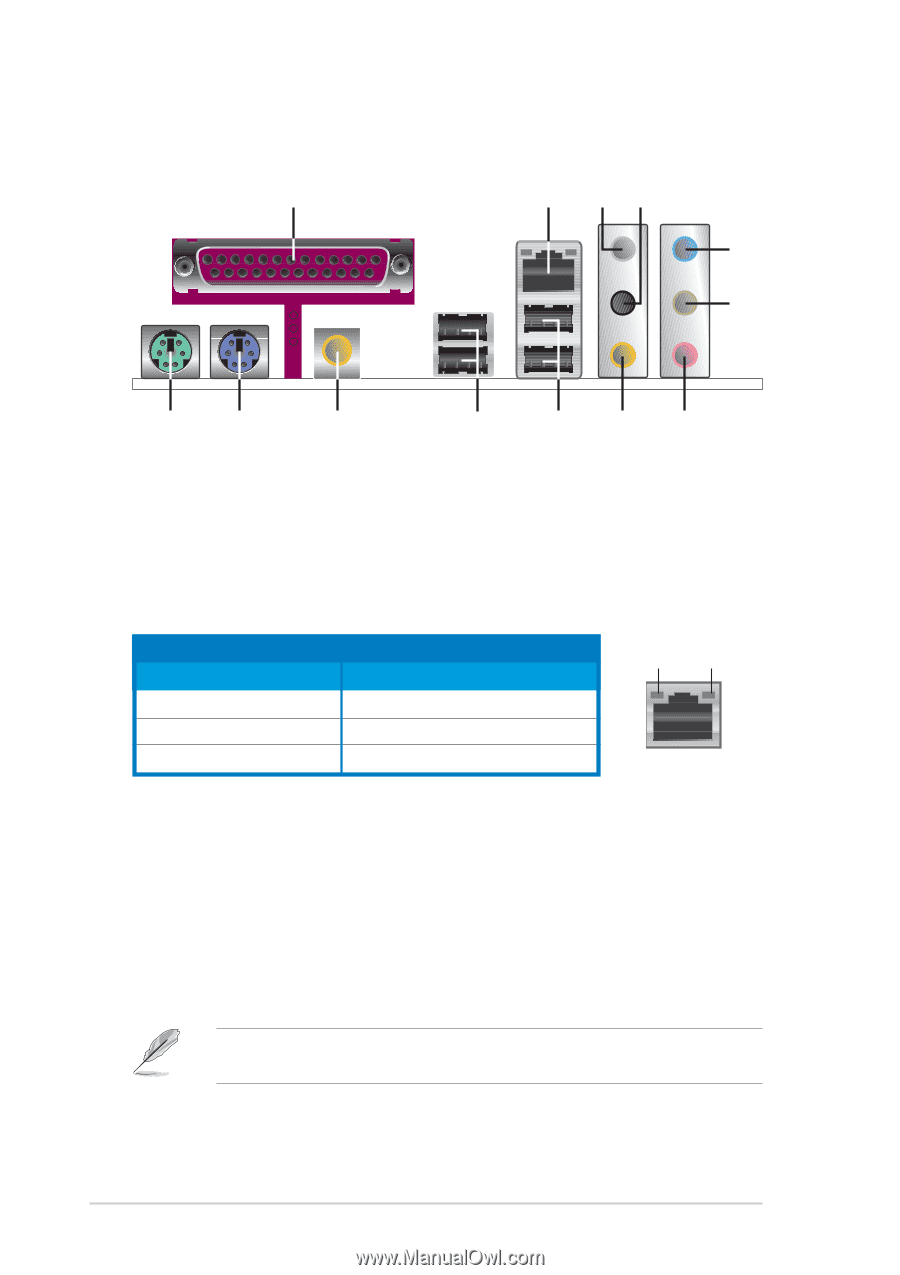
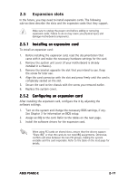
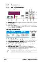
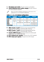
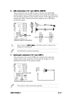
2.7 Connectors 2.7.1 Rear panel connectors 1 2 34 5 6 13 12 11 10 987 1 . P a r a l l e l p o r t . This 25-pin port connects a parallel printer, a scanner, or other devices. 2 . L A N ( R J - 4 5 ) p o r t . This port allows Gigabit connection to a Local Area Network (LAN) through a network hub. Refer to the table below for the LAN port LED indications. LAN port LED indications ACT/LINK LED SPEED LED Status Description Status Description OFF GREEN BLINKING No link Linked Data activity OFF ORANGE GREEN 10 Mbps connection 100 Mbps connection 1 Gbps connection ACT/LINK SPEED LED LED LAN port 3 . R e a r S p e a k e r O u t p o r t ( g r a y ) . This port connects the rear speakers on a 4-channel, 6-channel, or 8-channel audio configuration. 4 . S i d e S p e a k e r O u t p o r t ( b l a c k ) . This port connects the side speakers in an 8-channel audio configuration. 5 . L i n e I n p o r t ( l i g h t b l u e ) . This port connects a tape, CD, DVD player, or other audio sources. 6 . L i n e O u t p o r t ( l i m e ) . This port connects a headphone or a speaker. In 4-channel, 6-channel, and 8-channel configuration, the function of this port becomes Front Speaker Out. Refer to the audio configuration table on the next page for the function of the audio ports in 2, 4, 6, or 8-channel configuration. 2-22 Chapter 2: Hardware information

  • 1
  • 2
  • 3
  • 4
  • 5
  • 6
  • 7
  • 8
  • 9
  • 10
  • 11
  • 12
  • 13
  • 14
  • 15
  • 16
  • 17
  • 18
  • 19
  • 20
  • 21
  • 22
  • 23
  • 24
  • 25
  • 26
  • 27
  • 28
  • 29
  • 30
  • 31
  • 32
  • 33
  • 34
  • 35
  • 36
  • 37
  • 38
  • 39
  • 40
  • 41
  • 42
  • 43
  • 44
  • 45
  • 46
  • 47
  • 48
  • 49
  • 50
  • 51
  • 52
  • 53
  • 54
  • 55
  • 56
  • 57
  • 58
  • 59
  • 60
  • 61
  • 62
  • 63
  • 64
  • 65
  • 66
  • 67
  • 68
  • 69
  • 70
  • 71
  • 72
  • 73
  • 74
  • 75
  • 76
  • 77
  • 78
  • 79
  • 80
  • 81
  • 82
  • 83
  • 84
  • 85
  • 86
  • 87
  • 88
  • 89
  • 90
  • 91
  • 92
  • 93
  • 94
  • 95
  • 96
  • 97
  • 98
  • 99
  • 100
  • 101
  • 102
  • 103
  • 104
  • 105
  • 106
  • 107
  • 108
  • 109
  • 110
  • 111
  • 112
  • 113
  • 114
  • 115
  • 116
  • 117
  • 118
  • 119
  • 120
  • 121
  • 122

2-22
2-22
2-22
2-22
2-22
Chapter 2: Hardware information
2.7
Connectors
2.7.1
2.7.1
2.7.1
2.7.1
2.7.1
Rear panel connectors
1.
1.
1.
1.
1.
Parallel port.
Parallel port.
Parallel port.
Parallel port.
Parallel port. This 25-pin port connects a parallel printer, a scanner,
or other devices.
2.
2.
2.
2.
2.
LAN (RJ-45) port.
LAN (RJ-45) port.
LAN (RJ-45) port.
LAN (RJ-45) port.
LAN (RJ-45) port. This port allows Gigabit connection to a Local
Area Network (LAN) through a network hub. Refer to the table below
for the LAN port LED indications.
3.
3.
3.
3.
3.
Rear Speaker Out port (gray).
Rear Speaker Out port (gray). This port connects the rear
speakers on a 4-channel, 6-channel, or 8-channel audio configuration.
4.
4.
4.
4.
4.
Side Speaker Out port (black).
Side Speaker Out port (black). This port connects the side
speakers in an 8-channel audio configuration.
5.
5.
5.
5.
5.
Line In port (light blue).
Line In port (light blue). This port connects a tape, CD, DVD
player, or other audio sources.
6.
6.
6.
6.
6.
Line Out port (lime).
Line Out port (lime). This port connects a headphone or a
speaker. In 4-channel, 6-channel, and 8-channel configuration, the
function of this port becomes Front Speaker Out.
Refer to the audio configuration table on the next page for the function
of the audio ports in 2, 4, 6, or 8-channel configuration.
ACT/LINK LED
ACT/LINK LED
ACT/LINK LED
ACT/LINK LED
ACT/LINK LED
SPEED LED
SPEED LED
SPEED LED
SPEED LED
SPEED LED
Status
Status
Status
Status
Status
Description
Description
Description
Description
Description
Status
Status
Status
Status
Status
Description
Description
Description
Description
Description
OFF
No link
OFF
10 Mbps connection
GREEN
Linked
ORANGE
100 Mbps connection
BLINKING
Data activity
GREEN
1 Gbps connection
LAN port LED indications
LAN port
LAN port
LAN port
LAN port
LAN port
SPEED
SPEED
SPEED
SPEED
SPEED
LED
LED
LED
LED
LED
ACT/LINK
ACT/LINK
ACT/LINK
ACT/LINK
ACT/LINK
LED
LED
LED
LED
LED
9
1
2
11
3
12
13
8
4
5
7
6
10