Asus P5BV-C User Guide - Page 45
Serial ATA connectors 7-pin SATA1, SATA2, SATA3, SATA4, SATA, RAID5, SATA_RAID6, SATA_RAID7,
 |
UPC - 610839157372
View all Asus P5BV-C manuals
Add to My Manuals
Save this manual to your list of manuals |
Page 45 highlights
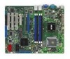
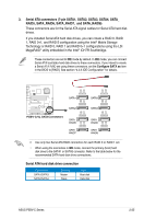
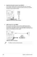
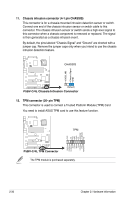
3. Serial ATA connectors (7-pin SATA1, SATA2, SATA3, SATA4, SATA_ RAID5, SATA_RAID6, SATA_RAID7, and SATA_RAID8) These connectors are for the Serial ATA signal cables for Serial ATA hard disk drives. If you installed Serial ATA hard disk drives, you can create a RAID 0, RAID 1, RAID 0+1, and RAID 5 configuration using the Intel® Matrix Storage Technology or RAID 0, RAID 1 and RAID 0+1 configurations using the LSI MegaRAID® utility embedded in the Intel® ICH7R Southbridge. These connectors are set to IDE mode by default. In IDE mode, you can connect Serial ATA boot/data hard disk drives to these connectors. If you intend to create a Serial ATA RAID set using these connectors, set the Configure SATA as item in the BIOS to [RAID]. See section "4.3.5 IDE Configuration" for details. GND RSATA_RXN2 RSATA_RXP2 GND RSATA_TXN2 RSATA_TXP2 GND GND RSATA_RXN1 RSATA_RXP1 GND RSATA_TXN1 RSATA_TXP1 GND ® P5BV-C/4L SATA1 SATA3 GND RSATA_RXN4 RSATA_RXP4 GND RSATA_TXN4 RSATA_TXP4 GND GND RSATA_RXN3 RSATA_RXP3 GND RSATA_TXN3 RSATA_TXP3 GND GND RSATA_RXN6 RSATA_RXP6 GND RSATA_TXN6 RSATA_TXP6 GND SATA2 P5BV-C/4L SATA Connectors SATA_ RAID5 SATA_ RAID7 GND RSATA_RXN7 RSATA_RXP7 GND RSATA_TXN7 RSATA_TXP7 GND GND RSATA_RXN5 RSATA_RXP5 GND RSATA_TXN5 RSATA_TXP5 GND SATA4 SATA_ RAID6 SATA_ RAID8 GND RSATA_RXN8 RSATA_RXP8 GND RSATA_TXN8 RSATA_TXP8 GND • Use only two Serial ATA RAID connectors for each RAID 0 or RAID 1 set. • When using the connectors in IDE mode, connect the primary (boot) hard disk drive to the SATA1 or SATA3 connector. Refer to the table below for the recommended SATA hard disk drive connections. Serial ATA hard disk drive connection Connector SATA1/SATA3 SATA2/SATA4 Setting Master Slave Use Boot disk Data disk ASUS P5BV-C Series 2-25
-
 1
1 -
2
-
3
-
4
-
5
-
6
-
7
-
8
-
9
-
10
-
11
-
12
-
13
-
14
-
15
-
16
-
17
-
18
-
19
-
20
-
21
-
22
-
23
-
24
-
25
-
26
-
27
-
28
-
29
-
30
-
31
-
32
-
33
-
34
-
35
-
36
-
37
-
38
-
39
-
 40
40 -
 41
41 -
 42
42 -
 43
43 -
 44
44 -
 45
45 -
 46
46 -
 47
47 -
 48
48 -
 49
49 -
 50
50 -
51
-
52
-
53
-
54
-
55
-
56
-
57
-
58
-
59
-
60
-
61
-
62
-
63
-
64
-
65
-
66
-
67
-
68
-
69
-
70
-
71
-
72
-
73
-
74
-
75
-
76
-
77
-
78
-
79
-
80
-
81
-
82
-
83
-
84
-
85
-
86
-
87
-
88
-
89
-
90
-
91
-
92
-
93
-
94
-
95
-
96
-
97
-
98
-
99
-
100
-
101
-
102
-
103
-
104
-
105
-
106
-
107
-
108
-
109
-
110
-
111
-
112
-
113
-
114
-
115
-
116
-
117
-
118
-
119
-
120
-
121
-
122
-
123
-
124
-
125
-
126
-
127
-
128
-
129
-
130
-
131
-
132
-
133
-
134
-
135
-
136
-
137
-
138
-
139
-
140
-
141
-
142
-
143
-
144
-
145
-
146
-
147
-
148
-
149
-
150
-
151
-
152
-
153
-
154
-
155
-
156
-
157
-
158
-
159
-
160
-
161
 |
 |