Asus P5G41T-M LX2 GB User Manual - Page 23
P5G41T-M LX2/GB/LPT Chassis intrusion connector - lpt bios
 |
View all Asus P5G41T-M LX2 GB manuals
Add to My Manuals
Save this manual to your list of manuals |
Page 23 highlights
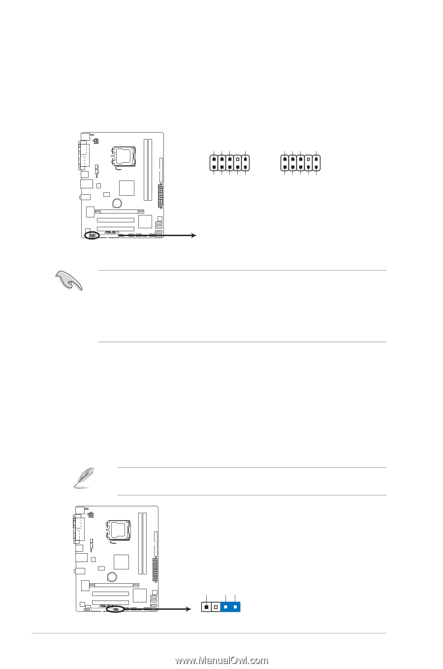
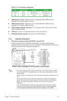
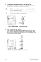
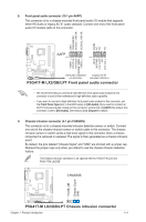
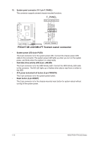
8. Front panel audio connector (10-1 pin AAFP) This connector is for a chassis-mounted front panel audio I/O module that supports either HD Audio or legacy AC`97 audio standard. Connect one end of the front panel audio I/O module cable to this connector. GND PRESENCE# SENSE1_RETUR SENSE2_RETUR AGND NC NC NC AAFP PIN 1 PIN 1 MIC2 MICPWR Line out_R NC Line out_L PORT1 L PORT1 R PORT2 R SENSE_SEND PORT2 L P5G41T-M LX2/GB/LPT HD-audio-compliant Legacy AC'97 pin definition compliant definition P5G41T-M LX2/GB/LPT Front panel audio connector • We recommend that you connect a high-definition front panel audio module to this connector to avail of the motherboard's high-definition audio capability. • If you want to connect a high-definition front panel audio module to this connector, set the Front Panel Type item in the BIOS setup to [HD Audio]. If you want to connect an AC'97 front panel audio module to this connector, set the item to [AC97]. By default, this connector is set to [HD Audio]. See section 2.4.2 Chipset for details. 9. Chassis intrusion connector (4-1 pin CHASSIS) This connector is for a chassis-mounted intrusion detection sensor or switch. Connect one end of the chassis intrusion sensor or switch cable to this connector. The chassis intrusion sensor or switch sends a high-level signal to this connector when a chassis component is removed or replaced. The signal is then generated as a chassis intrusion event. By default, the pins labeled "Chassis Signal" and "GND" are shorted with a jumper cap. Remove the jumper caps only when you intend to use the chassis intrusion detection feature. The Chassis intrusion connector is an optional item for P5G41T-M LX2 and P5G41T-M LX2/GB. CHASSIS +5VSB_MB Chassis Signal GND P5G41T-M LX2/GB/LPT P5G41T-M LX2/GB/LPT Chassis intrusion connector Chapter 1: Product introduction 1-14
-
 1
1 -
2
-
3
-
4
-
5
-
6
-
7
-
8
-
9
-
10
-
11
-
12
-
13
-
14
-
15
-
16
-
17
-
 18
18 -
 19
19 -
 20
20 -
 21
21 -
 22
22 -
 23
23 -
 24
24 -
 25
25 -
 26
26 -
 27
27 -
 28
28 -
29
-
30
-
31
-
32
-
33
-
34
-
35
-
36
-
37
-
38
-
39
-
40
 |
 |