Asus P5G41T-M LX2 User Manual
Asus P5G41T-M LX2 Manual
 |
View all Asus P5G41T-M LX2 manuals
Add to My Manuals
Save this manual to your list of manuals |
Asus P5G41T-M LX2 manual content summary:
- Asus P5G41T-M LX2 | User Manual - Page 1
Motherboard P5G41T-M LX2 Series • P5G41T-M LX2 • P5G41T-M LX2/GB • P5G41T-M LX2/GB/LPT - Asus P5G41T-M LX2 | User Manual - Page 2
ASUS"). Product warranty or service ASUS HAS BEEN ADVISED OF THE POSSIBILITY OF SUCH DAMAGES ARISING FROM ANY DEFECT OR ERROR IN THIS MANUAL OR PRODUCT. SPECIFICATIONS AND INFORMATION CONTAINED IN THIS MANUAL downloading it from http://support.asus.com/download; or encounter any problems in obtaining - Asus P5G41T-M LX2 | User Manual - Page 3
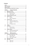
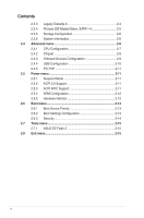
1.7 Connectors 1-9 1.7.1 Rear panel ports 1-9 1.7.2 Internal connectors 1-10 1.8 Software support 1-16 1.8.1 Installing an operating system 1-16 1.8.2 Support DVD information 1-16 Chapter 2: BIOS information 2.1 Managing and updating your BIOS 2-1 2.1.1 ASUS Update utility 2-1 2.1.2 ASUS EZ - Asus P5G41T-M LX2 | User Manual - Page 4
2-6 2.4 Advanced menu 2-6 2.4.1 CPU Configuration 2-7 2.4.2 Chipset 2-8 2.4.3 Onboard Devices Configuration 2-9 2.4.4 USB Configuration 2-10 2.4.5 PCI PnP 2-11 2.5 Power menu 2-11 2.5.1 Suspend Mode 2-11 2.5.2 ACPI 2.0 Support 2-11 2.5.3 ACPI APIC Support 2-11 2.5.4 APM Configuration 2-12 - Asus P5G41T-M LX2 | User Manual - Page 5
in accordance with manufacturer's instructions, may cause harmful interference the equipment off and on, the user is encouraged to try to correct the technician for help. The use of shielded cables for connection of the monitor to the products at ASUS REACH website at http://green.asus.com/english - Asus P5G41T-M LX2 | User Manual - Page 6
all the manuals that came with the package. • Before using the product, ensure that all cables are correctly connected and the power cables are encounter technical problems with the product, contact a qualified service technician or your retailer. About this guide This user guide contains the - Asus P5G41T-M LX2 | User Manual - Page 7
Instructions that you MUST follow to complete a task. NOTE: Tips and additional information to help you complete a task. Where to find more information Refer to the following sources for additional information and for product and software updates. 1. ASUS websites The ASUS website provides updated - Asus P5G41T-M LX2 | User Manual - Page 8
max. shared memory of 1759MB Supports RGB with max. resolution of 2048 x 1536 x 32Bpp @ 75HZ Supports Microsoft® DirectX 10 1 x PCIe x16 slot 1 x PCIe x1 slot (optional) 2 x PCI slots 1 x Ultra DMA 100/66 connector 4 x Serial ATA 3Gb/s ports P5G41T-M LX2/GB and P5G41T-M LX2/GB/LPT: Realtek® RTL8112L - Asus P5G41T-M LX2 | User Manual - Page 9
ports Internal connectors ASUS unique features BIOS Manageability Support DVD Accessories Form factor 1 x PS/2 keyboard port 1 x PS/2 mouse port 1 x COM port 1 x VGA port 1 x LAN (RJ-45) port 4 x USB 2.0/1.1 ports 1 x LPT port (optional for P5G41T-M LX2 and P5G41T-M LX2/GB) 6-channel audio ports - Asus P5G41T-M LX2 | User Manual - Page 10
down the system and unplug the power cable before removing or plugging in any motherboard component. The illustration below shows the location of the onboard LED. SB_PWR P5G41T-M LX2/GB/LPT ON OFF Standby Power Powered Off P5G41T-M LX2/GB/LPT Onboard power LED 1-1 ASUS P5G41T-M LX2 Series - Asus P5G41T-M LX2 | User Manual - Page 11
RTL8103EL Fast Ethernet controller. • P5G41T-M LX2/GB and P5G41T-M LX2/GB/LPT integrate the Realtek® RTL8112L Gigabit Ethernet controller. • The floppy disk drive connector, chassis intrusion connector, and LPT port are optional items for P5G41T-M LX2 and P5G41T-M LX2/GB. Place six screws into the - Asus P5G41T-M LX2 | User Manual - Page 12
the socket contacts resulting from incorrect CPU installation/removal, or misplacement/loss/incorrect removal of the PnP cap. The motherboard supports Intel® LGA775 processors with the Intel® Enhanced Intel SpeedStep® Technology (EIST) and Hyper-Threading Technology. 1-3 ASUS P5G41T-M LX2 Series - Asus P5G41T-M LX2 | User Manual - Page 13
with less power consumption. The figure illustrates the location of the DDR3 DIMM sockets: DIMM_A1 DIMM_B1 Channel Channel A Channel B Sockets DIMM_A1 DIMM_B1 P5G41T-M LX2/GB/LPT P5G41T-M LX2/GB/LPT 240-pin DDR3 DIMM sockets 1.4.2 Memory configurations You may install 512MB, 1GB, 2GB, and 4GB - Asus P5G41T-M LX2 | User Manual - Page 14
support: • A*: Supports one module inserted into either slot as Single-channel memory configuration. • B*: Supports one pair of modules inserted into both slots as one pair of dual-channel memory configuration. Visit the ASUS website at www.asus.com for the latest QVL. 1-5 ASUS P5G41T-M LX2 - Asus P5G41T-M LX2 | User Manual - Page 15
system unstable and the card inoperable. 1.5.3 PCI slots The PCI slot supports cards such as a LAN card, SCSI card, USB card, and other cards that comply with PCI specifications. 1.5.4 PCI Express x16 slot This motherboard supports a PCI Express x16 graphics card that complies with the PCI Express - Asus P5G41T-M LX2 | User Manual - Page 16
CMOS memory of date, time, and system setup parameters by erasing the CMOS RTC RAM data. The onboard button cell battery powers the RAM data in CMOS, which include system setup information such as system passwords. CLRTC 12 23 P5G41T-M LX2/GB/LPT Normal (Default) Clear RTC P5G41T-M LX2/GB/LPT - Asus P5G41T-M LX2 | User Manual - Page 17
BIOS. KBPWR 12 23 +5V +5VSB (Default) P5G41T-M LX2/GB/LPT P5G41T-M LX2/GB/LPT Keyboard Power Setting 3. USB device wake-up (3-pin USBPW1-4, USBPW5-8) Set these jumpers to +5V to wake up the computer from S1 sleep mode (CPU - Asus P5G41T-M LX2 | User Manual - Page 18
Connectors Rear panel ports 2 3 45 11 10 9 8 7 6 1. PS/2 mouse port (green). This port is for a PS/2 mouse. 2. LPT port. This 25-pin port connects to a parallel printer, a scanner, or other devices. The LPT port is an optional item for P5G41T-M LX2 and P5G41T-M LX2/GB. 3. LAN (RJ-45) port - Asus P5G41T-M LX2 | User Manual - Page 19
GND GND GND P5G41T-M LX2/GB/LPT +5 Volts GND PSON# GND +3 Volts -12 Volts +3 Volts +3 Volts PIN 1 P5G41T-M LX2/GB/LPT ATX power connectors • For a fully configured system, we recommend that you use a power supply unit (PSU) that complies with ATX 12V Specification 2.0 or later version - Asus P5G41T-M LX2 | User Manual - Page 20
! Only the 4-pin CPU fan supports the ASUS Q-Fan feature. P5G41T-M LX2/GB/LPT CHA_FAN Rotation +12V GND CPU_FAN CPU FAN PWM CPU FAN IN CPU FAN PWR GND P5G41T-M LX2/GB/LPT fan connectors 3. Serial ATA connectors (7-pin SATA1-4) These connectors are for the Serial ATA signal cables for Serial ATA - Asus P5G41T-M LX2 | User Manual - Page 21
following modes to configure your device. PIN1 PRI_IDE P5G41T-M LX2/GB/LPT NOTE:Orient the red markings on the IDE ribbon cable to PIN 1. P5G41T-M LX2/GB/LPT IDE connector Single device Two devices Drive jumper setting Cable-Select or Master Cable-Select Master Slave Mode of device(s) - Master - Asus P5G41T-M LX2 | User Manual - Page 22
with USB 2.0 specification that supports up to 480Mbps connection speed. USB+5V USB_P8USB_P8+ GND NC USB+5V USB_P6USB_P6+ GND NC P5G41T-M LX2/GB/LPT USB56 PIN 1 USB78 PIN 1 USB+5V USB_P7USB_P7+ GND USB+5V USB_P5USB_P5+ GND P5G41T-M LX2/GB/LPT USB2.0 connectors Never connect a 1394 cable to - Asus P5G41T-M LX2 | User Manual - Page 23
cable to this connector. GND PRESENCE# SENSE1_RETUR SENSE2_RETUR AGND NC NC NC AAFP PIN 1 PIN 1 MIC2 MICPWR Line out_R NC Line out_L PORT1 L PORT1 R PORT2 R SENSE_SEND PORT2 L P5G41T-M LX2/GB/LPT HD-audio-compliant Legacy AC'97 pin definition compliant definition P5G41T-M LX2/GB/LPT - Asus P5G41T-M LX2 | User Manual - Page 24
F_PANEL) This connector supports several chassis-mounted functions. F_PANEL PWR LED PWR BTN PIN 1 P5G41T-M LX2/GB/LPT HD LED RESET P5G41T-M LX2/GB/LPT System panel connector • System power LED (2-pin PLED) This 2-pin connector is for the system power LED. Connect the chassis power LED cable to this - Asus P5G41T-M LX2 | User Manual - Page 25
DVD are subject to change at any time without notice. Visit the ASUS website at www.asus.com for updates. To run the Support DVD Place the Support DVD to the optical drive. The DVD automatically displays the Drivers menu if Autorun is enabled in your computer. The following screen is for reference - Asus P5G41T-M LX2 | User Manual - Page 26
ASUS Update: 1. Place the support DVD in the optical drive. The Drivers menu appears. 2. Click the Utilities tab, then click ASUS Update. 3. Follow the onscreen instructions to complete the installation. Quit all Windows® applications before you update the BIOS using this utility. Updating the BIOS - Asus P5G41T-M LX2 | User Manual - Page 27
Current ROM BOARD:P5G41T-M LX2/GB/LPT VER:0305 (H:00 B:00) DATE: 10/29/2009 Update ROM BOARD: Unknown VER: Unknown DATE: Unknown PATH: A:\ A: Note [Enter] Select or Load [Tab] Switch [Up/Down/Home/End] Move [B] Backup [V] Drive Info [ESC] Exit • This function supports USB flash disks with - Asus P5G41T-M LX2 | User Manual - Page 28
(P5G41T-M LX2/GB/LPT). • The BIOS file in the support DVD may not be the latest version. Download the latest BIOS file from the ASUS website at www.asus.com. • The removable devices that ASUS CrashFree BIOS support vary with motherboard models. For motherboards without the floppy connector, prepare - Asus P5G41T-M LX2 | User Manual - Page 29
your screen. • Visit the ASUS website at www.asus.com to download the latest BIOS file for this motherboard. 2.3 Main menu When you enter the BIOS Setup program, the Main menu , 3.5 in.] [1.44M, 3.5 in.] [2.88M, 3.5 in.] This item is for P5G41T-M LX2/GB/LPT only. Chapter 2: BIOS information 2-4 - Asus P5G41T-M LX2 | User Manual - Page 30
/SATA device information. The BIOS automatically detects the values opposite monitoring). These values are not user-configurable. These items show Not Select CDROM if you are specifically configuring a CD-ROM time if the device supports multi-sector transfer feature. ASUS P5G41T-M LX2 Series - Asus P5G41T-M LX2 | User Manual - Page 31
] [Enhanced] Enhanced Mode Support On [S-ATA] Sets Serial specifications. The BIOS automatically detects the items in this menu. BIOS Information Displays the auto-detected BIOS information. Processor Displays the auto-detected CPU specification. System Memory Displays the auto-detected system memory - Asus P5G41T-M LX2 | User Manual - Page 32
CPU-related information that the BIOS automatically detects. Ratio CMOS Setting [Auto] Sets the ration between CPU core clock and the FSB frequency. Configuration option: [Auto] • If an invalid ratio is set in CMOS then actual and set values may differ. • Key in ratio numbers directly. C1E Support - Asus P5G41T-M LX2 | User Manual - Page 33
the front panel support type. If High Definition Audio Front Panel is used, set this item to [HD Audio]. Configuration options: [AC97] [HD Audio] Onboard Gigabit LAN [Enabled] Enables or disables the onboard LAN controller. Configuration options: [Enabled] [Disabled] For P5G41T-M LX2, this item - Asus P5G41T-M LX2 | User Manual - Page 34
item is for P5G41T-M LX2 and P5G41T-M LX2/GB without an LPT port at the back panel. Serial Port1 Mode [Normal] Selects the mode for Serial Port1. Configuration options: [Normal] The following item is for P5G41T-M LX2/GB/LPT with an LPT port at the back panel. Parallel Port Address [378] Allows - Asus P5G41T-M LX2 | User Manual - Page 35
USB devices at startup. If detected, the USB controller legacy mode is enabled. If no USB device is detected, the legacy USB support is disabled. Configuration options: [Disabled] [Enabled] [Auto] USB set the maximum time that the BIOS waits for the USB storage device to initialize. Configuration - Asus P5G41T-M LX2 | User Manual - Page 36
the memory size set to [No], BIOS configures all the devices support in the Application-Specific Integrated Circuit (ASIC). When this item is set to [Enabled], the ACPI APIC table pointer is included in the RSDT pointer list. Configuration options: [Disabled] [Enabled] 2-11 ASUS P5G41T-M LX2 - Asus P5G41T-M LX2 | User Manual - Page 37
+5VSB lead. Configuration options: [Disabled] [Enabled] 2.5.5 Hardware Monitor CPU Temperature [xxxºC/xxxºF] or [Ignored] MB Temperature [xxxºC/xxxºF] or CPU Q-Fan Function [Disabled] Enables or disables the CPU Q-Fan function. Configuration options: [Disabled] [Enabled] Chapter 2: BIOS information - Asus P5G41T-M LX2 | User Manual - Page 38
POST) while booting to decrease the time needed to boot the system. When set to [Disabled], BIOS performs all the POST items. Configuration options: [Disabled] [Enabled] Full Screen Logo [Enabled] This when error occurs. Configuration options: [Disabled] [Enabled] 2-13 ASUS P5G41T-M LX2 Series - Asus P5G41T-M LX2 | User Manual - Page 39
password, the other items appear to allow you to change other security settings. User Access Level [Full Access] This item allows you to select the access restriction to successfully. To change the user password, follow the same steps in setting a user password. Chapter 2: BIOS information 2-14 - Asus P5G41T-M LX2 | User Manual - Page 40
BIOS checks for the user password when you access the Setup utility. When this item is set to [Always], BIOS checks for the user Power BIOS SETUP UTILITY Boot Tools Exit ASUS EZ Flash 2 Press ENTER to run the utility to select and update BIOS. This utility supports 1.FAT ASUS P5G41T-M LX2
-
 1
1 -
 2
2 -
 3
3 -
 4
4 -
 5
5 -
 6
6 -
 7
7 -
8
-
9
-
10
-
11
-
12
-
13
-
14
-
15
-
16
-
17
-
18
-
19
-
20
-
21
-
22
-
23
-
24
-
25
-
26
-
27
-
28
-
29
-
30
-
31
-
32
-
33
-
34
-
35
-
36
-
37
-
38
-
39
-
40
 |
 |

Motherboard
P5G41T-M LX2 Series
• P5G41T-M LX2
• P5G41T-M LX2/GB
• P5G41T-M LX2/GB/LPT