Asus P5G41T-M LX2 User Manual - Page 11
Motherboard overview - intel motherboard
 |
View all Asus P5G41T-M LX2 manuals
Add to My Manuals
Save this manual to your list of manuals |
Page 11 highlights
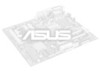
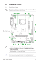
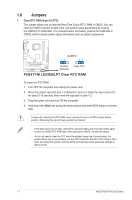
1.2 1.2.1 Motherboard overview Motherboard layout Ensure that you install the motherboard into the chassis in the correct orientation. The edge with external ports goes to the rear part of the chassis. 1 2 34 5 6 19.1cm(7.5in) KBMS KBPWR ATX12V COM1 DDR3 DIMM_A1 (64bit, 240-pin module) DDR3 DIMM_B1 (64bit, 240-pin module) LPT VGA CHA_FAN LGA775 CPU_FAN USB34 USBPW1-4 LAN1_USB12 Place this side towards the rear of the chassis. AUDIO RTL 8112L ICS 9LPRS441 Intel® G41 Lithium Cell CMOS Power PRI_IDE 7 2 24.4cm(9.6in) EATXPWR Super PCIEX16 I/O 17 P5G41T-M LX2/GB/LPT SATA4 SATA3 8Mb PCI1 Intel® SATA2 BIOS SATA1 ICH7 PCI2 8 VIA VT1705 CD FLOPPY SB_PWR USBPW5-8 USB56 USB78 CLRTC AAFP CHASSIS F_PANEL 16 15 14 4 13 12 11 10 9 • P5G41T-M LX2 integrates the Realtek® RTL8103EL Fast Ethernet controller. • P5G41T-M LX2/GB and P5G41T-M LX2/GB/LPT integrate the Realtek® RTL8112L Gigabit Ethernet controller. • The floppy disk drive connector, chassis intrusion connector, and LPT port are optional items for P5G41T-M LX2 and P5G41T-M LX2/GB. Place six screws into the holes indicated by circles to secure the motherboard to the chassis. DO NOT overtighten the screws! Doing so can damage the motherboard. Chapter 1: Product introduction 1-2
-
 1
1 -
2
-
3
-
4
-
5
-
 6
6 -
 7
7 -
 8
8 -
 9
9 -
 10
10 -
 11
11 -
 12
12 -
 13
13 -
 14
14 -
 15
15 -
 16
16 -
17
-
18
-
19
-
20
-
21
-
22
-
23
-
24
-
25
-
26
-
27
-
28
-
29
-
30
-
31
-
32
-
33
-
34
-
35
-
36
-
37
-
38
-
39
-
40
 |
 |