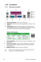
Asus P5GC-VM User Manual - Page 41
Serial ATA hard disk drive connection
 |
View all Asus P5GC-VM manuals
Add to My Manuals
Save this manual to your list of manuals |
Page 41 highlights
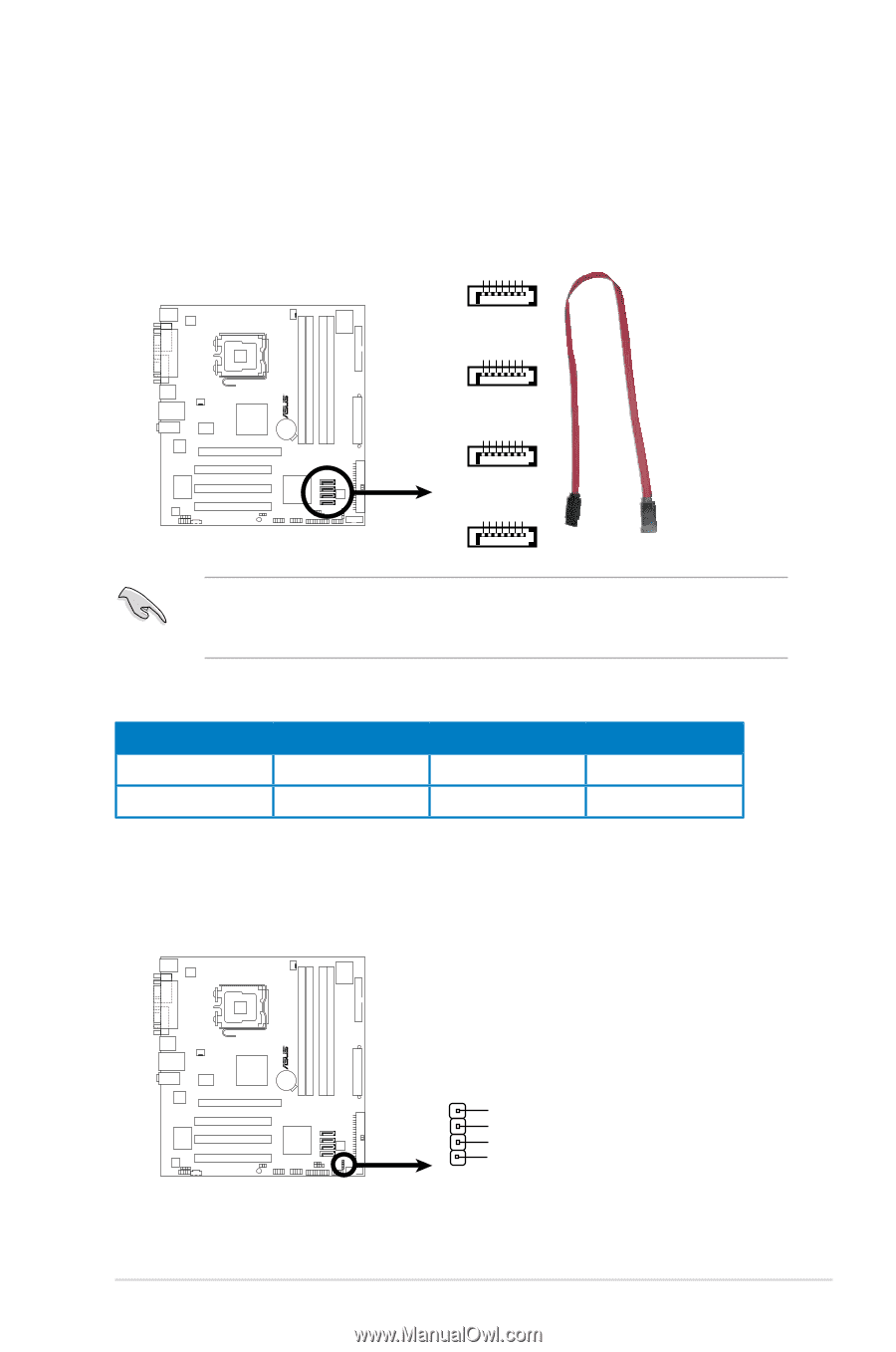
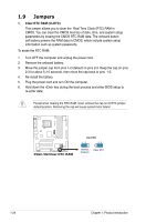
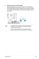
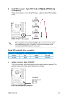
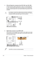
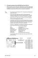
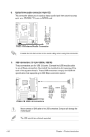
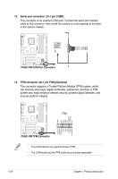
3. Serial ATA connectors (7-pin SATA1 [red], SATA2 [red], SATA3 [black], SATA4 [black]) These connectors are for the Serial ATA signal cables for Serial ATA hard disk drives. GND RSATA_RXN4 RSATA_RXP4 GND RSATA_TXN4 RSATA_TXP4 GND SATA4 GND RSATA_RXN3 RSATA_RXP3 GND RSATA_TXN3 RSATA_TXP3 GND SATA3 R P5GC-VM GND RSATA_RXN2 RSATA_RXP2 GND RSATA_TXN2 RSATA_TXP2 GND SATA2 GND RSATA_RXN1 RSATA_RXP1 GND RSATA_TXN1 RSATA_TXP1 GND SATA1 P5GC-VM SATA Connectors When using the connectors in Standard IDE mode, connect the primary (boot) hard disk drive to the SATA1/2 connector. Refer to the table below for the recommended SATA hard disk drive connections. Serial ATA hard disk drive connection Connector SATA1/2 SATA3/4 Color Red Black Setting Master Slave Use Boot disk Data Disk 4. Speaker connector (4-pin SPEAKER) This 4-pin connector is for the chassis-mounted system warning speaker. The speaker allows you to hear system beeps and warnings. R P5GC-VM SPEAKER 1 P5GC-VM Speaker Out Connector Speaker Out GND GND +5V ASUS P5GC-VM 1-29
-
 1
1 -
2
-
3
-
4
-
5
-
6
-
7
-
8
-
9
-
10
-
11
-
12
-
13
-
14
-
15
-
16
-
17
-
18
-
19
-
20
-
21
-
22
-
23
-
24
-
25
-
26
-
27
-
28
-
29
-
30
-
31
-
32
-
33
-
34
-
35
-
 36
36 -
 37
37 -
 38
38 -
 39
39 -
 40
40 -
 41
41 -
 42
42 -
 43
43 -
 44
44 -
 45
45 -
 46
46 -
47
-
48
-
49
-
50
-
51
-
52
-
53
-
54
-
55
-
56
-
57
-
58
-
59
-
60
-
61
-
62
-
63
-
64
-
65
-
66
-
67
-
68
-
69
-
70
-
71
-
72
-
73
-
74
-
75
-
76
-
77
-
78
-
79
-
80
-
81
-
82
-
83
-
84
-
85
-
86
-
87
-
88
-
89
-
90
-
91
-
92
-
93
-
94
 |
 |