Asus P5KPL-AM EPU User Manual - Page 16
Motherboard layout, Layout contents - audio
 |
View all Asus P5KPL-AM EPU manuals
Add to My Manuals
Save this manual to your list of manuals |
Page 16 highlights
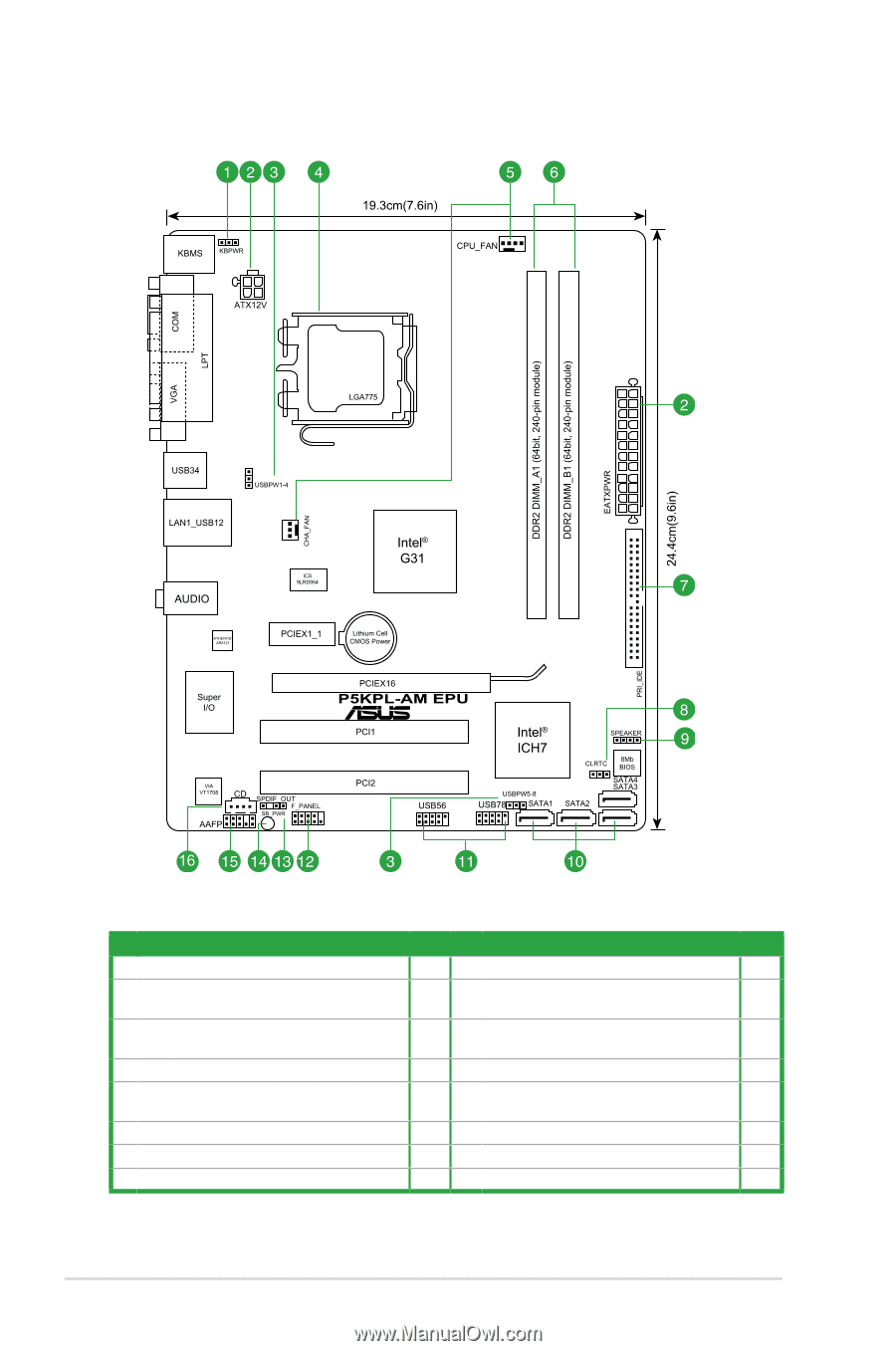
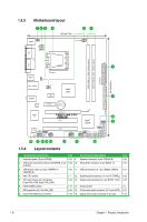
1.5.3 Motherboard layout 1.5.4 Layout contents Connectors/Jumpers/Slots Page Connectors/Jumpers/Slots Page 1. Keyboard power (3-pin KBPWR) 1-20 9. Speaker connector (4-pin SPEAKER) 1-26 2. ATX power connectors (24-pin EATXPWR, 4-pin 1-23 10. Serial ATA connectors (7-pin SATA1-4) 1-24 ATX12V) 3. USB device wake-up (3-pin USBPW1-4, USBPW5-8) 1-20 11. USB connectors (10-1 pin USB56, USB78) 1-27 4. Intel CPU socket 1-7 12. System panel connector (10-1 pin F_PANEL) 1-26 5. CPU and chassis fan connectors (4-pin CPU_FAN, 3-pin CHA_FAN) 1-22 13. Digital audio connector (4-1 pin SPDIF_OUT) 1-23 6. DDR2 DIMM sockets 1-12 14. Onboard LED 1-4 7. IDE connector (40-1 pin PRI_IDE) 1-25 15. Front panel audio connector (10-1 pin AAFP) 1-27 8. Clear RTC RAM (3-pin CLRTC) 1-19 16. Optical drive audio connector (4-pin CD) 1-24 1-6 Chapter 1: Product introduction
-
 1
1 -
2
-
3
-
4
-
5
-
6
-
7
-
8
-
9
-
10
-
 11
11 -
 12
12 -
 13
13 -
 14
14 -
 15
15 -
 16
16 -
 17
17 -
 18
18 -
 19
19 -
 20
20 -
 21
21 -
22
-
23
-
24
-
25
-
26
-
27
-
28
-
29
-
30
-
31
-
32
-
33
-
34
-
35
-
36
-
37
-
38
-
39
-
40
-
41
-
42
-
43
-
44
-
45
-
46
-
47
-
48
-
49
-
50
-
51
-
52
-
53
-
54
-
55
-
56
-
57
-
58
-
59
-
60
 |
 |