Asus P5KPL-AM IN GB User Manual - Page 20
IDE connector 40-1 pin PRI_IDE, Speaker connector 4-pin SPEAKER - drivers
 |
View all Asus P5KPL-AM IN GB manuals
Add to My Manuals
Save this manual to your list of manuals |
Page 20 highlights
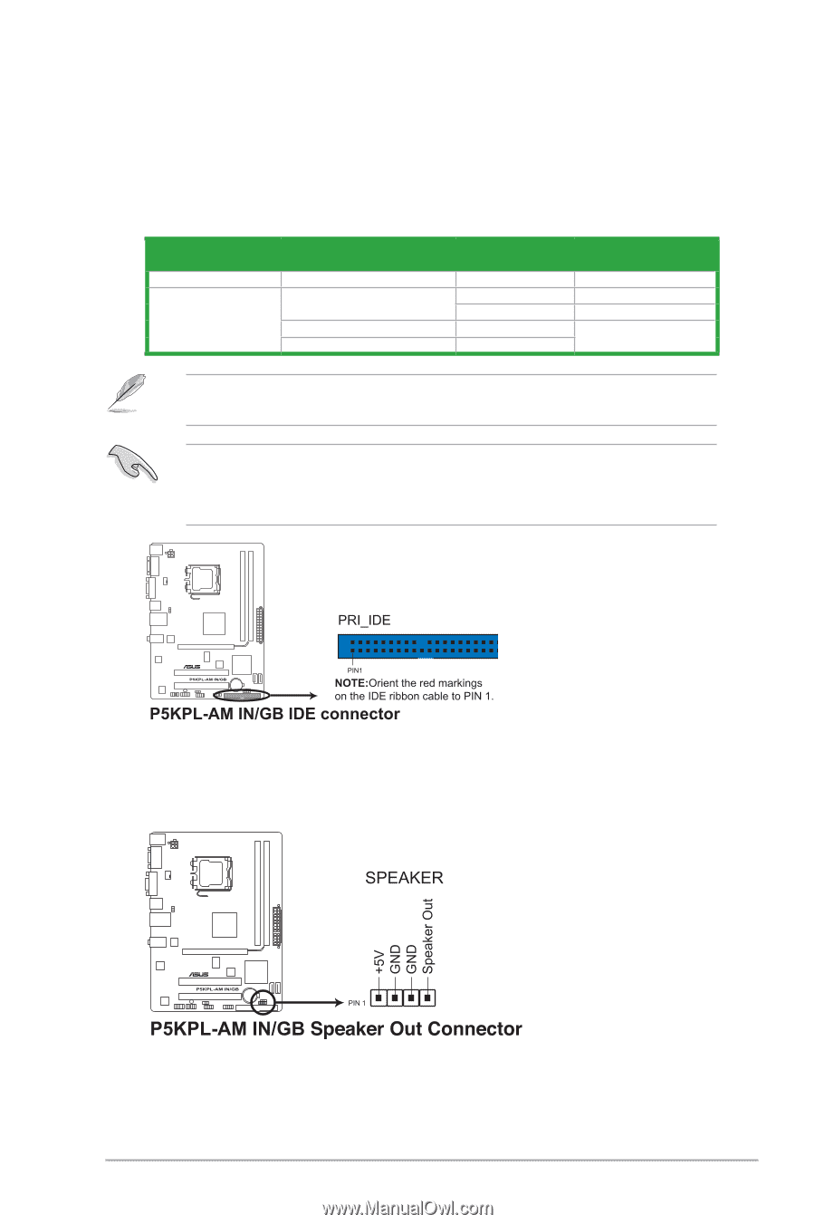
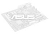
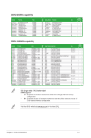
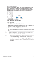
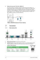
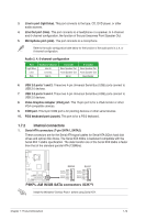
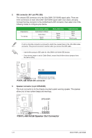
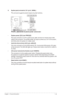
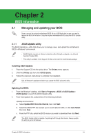
2. IDE connector (40-1 pin PRI_IDE) The onboard IDE connector is for the Ultra DMA 133/100/66 signal cable. There are three connectors on each Ultra DMA 133/100/66 signal cable: blue, black, and gray. Connect the blue connector to the motherboard's IDE connector, then select one of the following modes to configure your device. Single device Two devices Driver Jumper setting Cable-Select or Master Cable-Select Master Slave Mode of device(s) Master Slave Master Slave Cable connector Black Black Gray Black or gray Pin 20 on the IDE connector is removed to match the covered hole on the Ultra DMA cable connector. This prevents incorrect insertion when you connect the IDE cable. • Use the 80-conductor IDE cable for Ultra DMA 133/100/66 IDE devices. • If any device jumper is set to Cable-Select, ensure that all other device jumpers have the same setting. 3. Speaker connector (4-pin SPEAKER) This 4-pin connector is for the chassis-mounted system warning speaker. The speaker allows you to hear system beeps and warnings. 1-11 ASUS P5KPL-AM IN/GB
-
 1
1 -
2
-
3
-
4
-
5
-
6
-
7
-
8
-
9
-
10
-
11
-
12
-
13
-
14
-
 15
15 -
 16
16 -
 17
17 -
 18
18 -
 19
19 -
 20
20 -
 21
21 -
 22
22 -
 23
23 -
 24
24 -
 25
25 -
26
-
27
-
28
-
29
-
30
-
31
-
32
-
33
-
34
-
35
-
36
-
37
-
38
-
39
-
40
 |
 |