Asus P5L 1394 Motherboard Installation Guide - Page 44
Internal connectors
 |
View all Asus P5L 1394 manuals
Add to My Manuals
Save this manual to your list of manuals |
Page 44 highlights
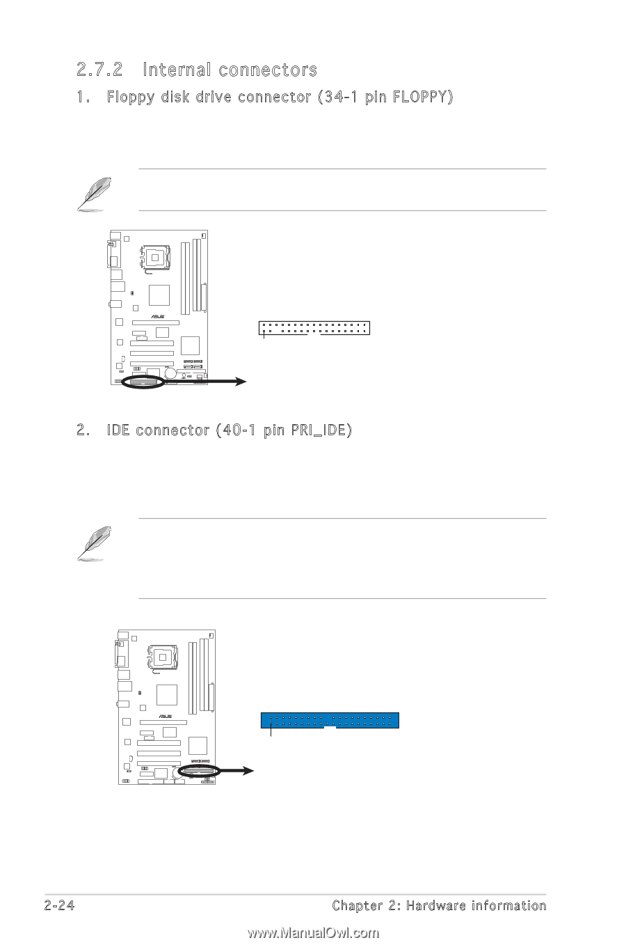
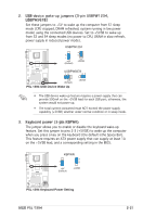
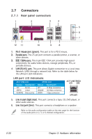
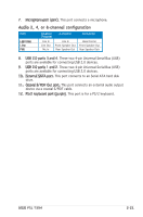
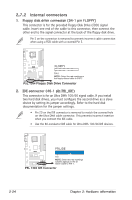
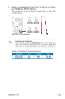
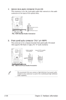
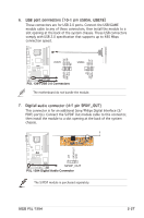
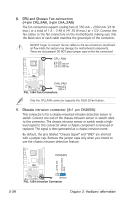
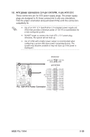
2.7.2 Internal connectors 1. Floppy disk drive connector (34-1 pin FLOPPY) This connector is for the provided Floppy Disk Drive (FDD) signal cable. Insert one end of the cable to this connector, then connect the other end to the signal connector at the back of the floppy disk drive. Pin 5 on the connector is removed to prevent incorrect cable connection when using a FDD cable with a covered Pin 5. P5L 1394 R FLOPPY PIN 1 NOTE: Orient the red markings on the floppy ribbon cable to PIN 1. P5L 1394 Floppy Disk Drive Connector 2. IDE connector (40-1 pin PRI_IDE) This connector is for an Ultra DMA 100/66 signal cable. If you install two hard disk drives, you must configure the second drive as a slave device by setting its jumper accordingly. Refer to the hard disk documentation for the jumper settings. • Pin 20 on the IDE connector is removed to match the covered hole on the Ultra DMA cable connector. This prevents incorrect insertion when you connect the IDE cable. • Use the 80-conductor IDE cable for Ultra DMA 100/66 IDE devices. P5L 1394 PRI_IDE R PIN1 NOTE: Orient the red markings (usually zigzag) on the ID ribbon cable to PIN 1. P5L 1394 IDE Connector 2-24 Chapter 2: Hardware information
-
 1
1 -
2
-
3
-
4
-
5
-
6
-
7
-
8
-
9
-
10
-
11
-
12
-
13
-
14
-
15
-
16
-
17
-
18
-
19
-
20
-
21
-
22
-
23
-
24
-
25
-
26
-
27
-
28
-
29
-
30
-
31
-
32
-
33
-
34
-
35
-
36
-
37
-
38
-
 39
39 -
 40
40 -
 41
41 -
 42
42 -
 43
43 -
 44
44 -
 45
45 -
 46
46 -
 47
47 -
 48
48 -
 49
49 -
50
-
51
-
52
-
53
-
54
-
55
-
56
-
57
-
58
-
59
-
60
-
61
-
62
-
63
-
64
-
65
-
66
-
67
-
68
-
69
-
70
-
71
-
72
-
73
-
74
-
75
-
76
-
77
-
78
-
79
-
80
-
81
-
82
-
83
-
84
-
85
-
86
-
87
-
88
-
89
-
90
-
91
-
92
-
93
-
94
-
95
-
96
-
97
-
98
-
99
-
100
-
101
-
102
-
103
-
104
-
105
-
106
-
107
-
108
-
109
-
110
-
111
-
112
-
113
-
114
-
115
-
116
-
117
-
118
-
119
-
120
 |
 |