Asus P5N32-E SLI Plus P5N32-E SLI Plus User''s Manual for English Edtion - Page 57
ATX power connectors, pin EATXPWR, 2 x 4-pin ATX12V, Chassis intrusion connector 4-1 pin CHASSIS
 |
View all Asus P5N32-E SLI Plus manuals
Add to My Manuals
Save this manual to your list of manuals |
Page 57 highlights
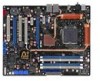
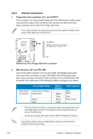
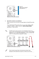
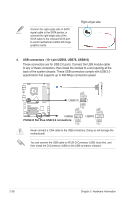
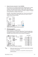
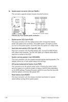
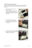
7. Chassis intrusion connector (4-1 pin CHASSIS) This connector is for a chassis-mounted intrusion detection sensor or switch. Connect one end of the chassis intrusion sensor or switch cable to this connector. The chassis intrusion sensor or switch sends a high-level signal to this connector when a chassis component is removed or replaced. The signal is then generated as a chassis intrusion event. By default , the pin labeled "Chassis Signal" and " Ground" are shorted with a jumper cap. Remove the jumper caps only when you intend to use the chassis intrusion detection feature. +5VSB_MB Chassis Signal GND ® P5N32-E SLI Plus CHASSIS (Default) P5N32-E SLI Plus Chassis intrusion connector 8. ATX power connectors (24-pin EATXPWR, 2 x 4-pin ATX12V) These connectors are for ATX power supply plugs. The power supply plugs are designed to fit these connectors in only one orientation. Find the proper orientation and push down firmly until the connectors completely fit. ATX12V ® P5N32-E SLI Plus P5N32-E SLI Plus ATX power connectors GND GND GND GND +12V DC +12V DC +12V DC +12V DC EATXPWR +3 Volts +12 Volts +12 Volts +5V Standby Power OK Ground +5 Volts Ground +5 Volts Ground +3 Volts +3 Volts Ground +5 Volts +5 Volts +5 Volts -5 Volts Ground Ground Ground PSON# Ground -12 Volts +3 Volts • Make sure to remove the cap on the ATX12V connector before connecting an 8-pin EPS +12V power plug. • Use only either a 4-pin ATX12V or an 8-pin EPS +12V power plug for the ATX12V connector. ASUS P5N32-E SLI Plus 2-31
-
 1
1 -
2
-
3
-
4
-
5
-
6
-
7
-
8
-
9
-
10
-
11
-
12
-
13
-
14
-
15
-
16
-
17
-
18
-
19
-
20
-
21
-
22
-
23
-
24
-
25
-
26
-
27
-
28
-
29
-
30
-
31
-
32
-
33
-
34
-
35
-
36
-
37
-
38
-
39
-
40
-
41
-
42
-
43
-
44
-
45
-
46
-
47
-
48
-
49
-
50
-
51
-
 52
52 -
 53
53 -
 54
54 -
 55
55 -
 56
56 -
 57
57 -
 58
58 -
 59
59 -
 60
60 -
 61
61 -
 62
62 -
63
-
64
-
65
-
66
-
67
-
68
-
69
-
70
-
71
-
72
-
73
-
74
-
75
-
76
-
77
-
78
-
79
-
80
-
81
-
82
-
83
-
84
-
85
-
86
-
87
-
88
-
89
-
90
-
91
-
92
-
93
-
94
-
95
-
96
-
97
-
98
-
99
-
100
-
101
-
102
-
103
-
104
-
105
-
106
-
107
-
108
-
109
-
110
-
111
-
112
-
113
-
114
-
115
-
116
-
117
-
118
-
119
-
120
-
121
-
122
-
123
-
124
-
125
-
126
-
127
-
128
-
129
-
130
-
131
-
132
-
133
-
134
-
135
-
136
-
137
-
138
-
139
-
140
-
141
-
142
-
143
-
144
-
145
-
146
-
147
-
148
-
149
-
150
-
151
-
152
-
153
-
154
-
155
-
156
-
157
-
158
 |
 |