Asus P5QL-EM User Manual - Page 35
Front panel audio connector 10-1 pin AAFP, P5QL-EM, Front Panel Audio Connector, Chassis intrusion
 |
UPC - 610839163038
View all Asus P5QL-EM manuals
Add to My Manuals
Save this manual to your list of manuals |
Page 35 highlights
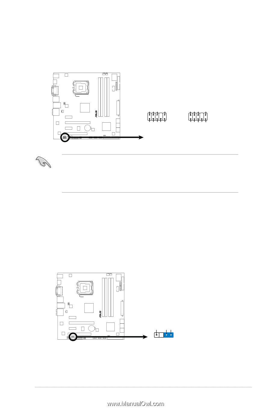
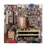
7. Front panel audio connector (10-1 pin AAFP) This connector is for a chassis-mounted front panel audio I/O module that supports either HD Audio or legacy AC`97 audio standard. Connect one end of the front panel audio I/O module cable to this connector. AAFP HD-audio-compliant pin definition Legacy AC'97 compliant definition GND PRESENSE# SENSE1_RETUR SENSE2_RETUR P5QL-EM AGND NC NC NC R MIC2 MICPWR Line out_R NC Line out_L PORT1L PORT1R PORT2R SEBSE_SEND PORT2L P5QL-EM.Front.Panel.Audio.Connector • We recommend that you connect a high-definition front panel audio module to this connector to avail of the motherboard's high-definition audio capability. • By default, this connector is set to HD Audio. If you want to connect an AC97 front panel audio module to this connector, set the Front Panel Support Type item in the BIOS to [AC97]. See section "2.4.4 Chipset" for details. 8. Chassis intrusion connector (4-1 pin CHASSIS) This connector is for a chassis-mounted intrusion detection sensor or switch. Connect one end of the chassis intrusion sensor or switch cable to this connector. The chassis intrusion sensor or switch sends a high-level signal to this connector when a chassis component is removed or replaced. The signal is then generated as a chassis intrusion event. By default, the pins labeled "Chassis Signal" and "Ground" are shorted with a jumper cap. Remove the jumper caps only when you intend to use the chassis intrusion detection feature. CHASSIS P5QL-EM +5VSB_MB Chassis Signal GND R P5QL-EM.Intrusion.Connector (Default) ASUS P5QL-EM 1-25
-
 1
1 -
2
-
3
-
4
-
5
-
6
-
7
-
8
-
9
-
10
-
11
-
12
-
13
-
14
-
15
-
16
-
17
-
18
-
19
-
20
-
21
-
22
-
23
-
24
-
25
-
26
-
27
-
28
-
29
-
 30
30 -
 31
31 -
 32
32 -
 33
33 -
 34
34 -
 35
35 -
 36
36 -
 37
37 -
 38
38 -
 39
39 -
 40
40 -
41
-
42
-
43
-
44
-
45
-
46
-
47
-
48
-
49
-
50
-
51
-
52
-
53
-
54
-
55
-
56
-
57
-
58
-
59
-
60
-
61
-
62
-
63
-
64
 |
 |